Calling all USS Hornet CV-8 fans

Carriers of all Nations and eras
CV, CVA, CVE, CVL, CVA, CVS, CVN.

Moderators: BB62vet, MartinJQuinn, Timmy C, Gernot, Olaf Held, Dan K, HMAS, ModelMonkey

Post Reply
User avatar
Iceman 29
Posts: 1945
Joined: Tue Sep 29, 2020 4:35 pm
Location: Bretagne, France

Re: Calling all USS Hornet CV-8 fans

Post by Iceman 29 »

Good view!

Probably the same net as those stored on the starboard side above the gangway.

Image
Pascal

�Battleship Bretagne 3D: https://vu.fr/FvCY
�SS Delphine 3D: https://vu.fr/NeuO
�SS Nomadic 3D: https://vu.fr/tAyL
�USS Nokomis 3D: https://vu.fr/kntC
�USS Pamanset 3D: https://vu.fr/jXGQ
User avatar
MartinJQuinn
Posts: 8506
Joined: Tue Jan 11, 2005 1:40 pm
Location: New Jersey

Re: Calling all USS Hornet CV-8 fans

Post by MartinJQuinn »

A few more CV-8 related questions, on this anniversary of her demise....
HornetIsland03_LI.jpg
1 - What's this? A pelorus?
2 - Any better shots of this area where the siren is? I have tons of photos from NARA, I've perused all the usual sites, but this is the best I can find
3 - what's this skinny pole on top of the main mast?

Here's a crop of the siren area
HornetIsland03 (2).jpg
HornetIsland03 (2).jpg (52.62 KiB) Viewed 8501 times
Trying to dress up the island with a bit more detail.
350HornetIsland.jpg
Martin

"Tomorrow is the most important thing in life. Comes into us at midnight very clean. It's perfect when it arrives and it puts itself in our hands. It hopes we've learned something from yesterday." John Wayne

Ship Model Gallery
User avatar
MartinJQuinn
Posts: 8506
Joined: Tue Jan 11, 2005 1:40 pm
Location: New Jersey

Re: Calling all USS Hornet CV-8 fans

Post by MartinJQuinn »

The searchlights look like they are painted a darker color than the the rest of the island. What's the consensus - black?
Martin

"Tomorrow is the most important thing in life. Comes into us at midnight very clean. It's perfect when it arrives and it puts itself in our hands. It hopes we've learned something from yesterday." John Wayne

Ship Model Gallery
User avatar
John W.
Posts: 518
Joined: Tue Mar 27, 2007 12:34 pm
Location: Smithfield, Virginia

Re: Calling all USS Hornet CV-8 fans

Post by John W. »

Martin -
Fine looking work there. Very impressive.

I might be able to shed some light on your questions, but I don't have a good HD version of the picture to which you refer. Having said that, do you have a copy of Davis Doyle's recent book on HORNET? If so, check out page 50. The photo shows the general area to which you are pointing with arrow #1. The photo is looking aft, taken from forward of that area (just aft of the Mk 37 director). There is what looks like a DF loop in the area where your arrow points. In some photos, the loop is apparently turned perpendicular to ship centerline and is not clearly seen as a loop. It does show up as a loop in the MD Silver plans (p.43). Also in the page 50 photo, just inside the splinter shield / windbreak on the port side is an odd looking device shaped kinda like a carronade. It does not show on the MD Silver plans. But forward of the spot where the picture was taken and inside the shield around the Mk. 37 there is a notation there calling out a "target designator" (p. 28). The plans show one to port, one to starboard. Not sure which of the devices your arrow could be highlighting, though, but here's a veritable "52 Pickup" of choices for you! OBTW, on pages 53, 55, and 56 in Doyle there are photos that show the searchlights mounted to the stack - port and starboard - that do appear darker than surrounding painted areas. I can see no obvious reason for the color differences other than different paint color.

Arrow #2 - The plans do not show the ship's horn / whistle in that location so I have nothing that tells me anymore than what you show. MD Silver plans (p. 92) show a decent view of the "Loud Speaker Foundation" close to the middle uptake as shown in the picture. But no similar foundation for the horn anywhere on the top of the stack. It might have been moved up there in the post-commissioning yard period in Jan / Feb '42 to get better sound coverage. Doyle's book on CV-5 (P. 40) shows YORKTOWN's horn located on the stack's centerline at the forward edge, and at about the same height as CV-8's. The foundation is more elaborate.

Arrow #3 - MD Silver plans (p. 81) indicate the top section of the Mainmast is a (wait for it . . .) "Flag Staff". At the very top is a flat device call a "Trident" (???) with halyards attached. The flagstaff appears to slide down along the starboard side of the mast for bridge clearance. Page 80 shows how the Foremast hinges aft also to clear bridges.

HTH
Some people make you happy, then they leave.
Others make you happy when they leave. (apologies to Oscar Wilde if he ever said anything similar, of which there is some doubt . . .)
User avatar
MartinJQuinn
Posts: 8506
Joined: Tue Jan 11, 2005 1:40 pm
Location: New Jersey

Re: Calling all USS Hornet CV-8 fans

Post by MartinJQuinn »

Thanks John - appreciate your comments and the info. I'd love to get a better look at the structure that DF loop sits on - it doesn't seem to sit on the deck, surrounded by a cage, as on CV-5 and CV-6, but appears to be raised.

One last question - do the MS plans indicate what the antenna in front of the forward Mk37 director is? There's a small pole and antenna there, and I can't figure out what it is.
Martin

"Tomorrow is the most important thing in life. Comes into us at midnight very clean. It's perfect when it arrives and it puts itself in our hands. It hopes we've learned something from yesterday." John Wayne

Ship Model Gallery
User avatar
John W.
Posts: 518
Joined: Tue Mar 27, 2007 12:34 pm
Location: Smithfield, Virginia

Re: Calling all USS Hornet CV-8 fans

Post by John W. »

Martin -
SPECINT alert. The following based on speculative intelligence.

The DF loop is pretty large, therefore I suspect it is used for ship's navigation - deriving a line of bearing to a shore transmitter most likely, - as opposed to the small loops located at and under the aft flight deck rounddown. The construction plans for HORNET show three bar railings in a number of places on the upper island structure which were later replaced by splinter shields during the yard period before she sailed for the Pac. I am guessing the loop was raised up on a small, probably circular structure so the loop could have a clear sight line above the steel splinter shield / windbreak.

The small antenna forward of the Mk 37 and atop the pilot house roof is actually a hamburger cooker - one of those rectangular mesh devices where you put the burger between the two sides and close it the device so it doesn't drop the burger on the charcoal.
No, probably not buying that I'll bet. Oh well, in that case turn to Doyle's CV-8 book, pages 54, 55, 58, 59, and 60 and you'll see the antenna. Looks like a small rectangular radar antenna similar to a BI (see Doyle CV-8 book p. 49). Similar but not the same. The photos on p. 54, 55, 59 show the antenna apparently horizontal, the two shots on p. 58 and 60 show it apparently vertical. The shot on p. 60 is particularly cool as it shows most of the antenna grid visible against a light backdrop. Perhaps it is a small backup surface search radar for entry to a foggy port.

End SPECINT.
Some people make you happy, then they leave.
Others make you happy when they leave. (apologies to Oscar Wilde if he ever said anything similar, of which there is some doubt . . .)
User avatar
MartinJQuinn
Posts: 8506
Joined: Tue Jan 11, 2005 1:40 pm
Location: New Jersey

Re: Calling all USS Hornet CV-8 fans

Post by MartinJQuinn »

John W. wrote:The small antenna forward of the Mk 37 and atop the pilot house roof is actually a hamburger cooker - one of those rectangular mesh devices where you put the burger between the two sides and close it the device so it doesn't drop the burger on the charcoal.
LOL. Thanks John. I'll go back through the Doyle book and look at the pages mentioned.
Martin

"Tomorrow is the most important thing in life. Comes into us at midnight very clean. It's perfect when it arrives and it puts itself in our hands. It hopes we've learned something from yesterday." John Wayne

Ship Model Gallery
User avatar
John W.
Posts: 518
Joined: Tue Mar 27, 2007 12:34 pm
Location: Smithfield, Virginia

Re: Calling all USS Hornet CV-8 fans

Post by John W. »

I note the antenna shows up in your picture posted above, now that I know what I'm looking for - looks like a "T" forward of the Mk.37 peeking just above the splinter shield / windbreak above the pilothouse windows.
Some people make you happy, then they leave.
Others make you happy when they leave. (apologies to Oscar Wilde if he ever said anything similar, of which there is some doubt . . .)
User avatar
MartinJQuinn
Posts: 8506
Joined: Tue Jan 11, 2005 1:40 pm
Location: New Jersey

Re: Calling all USS Hornet CV-8 fans

Post by MartinJQuinn »

John W. wrote:I note the antenna shows up in your picture posted above, now that I know what I'm looking for - looks like a "T" forward of the Mk.37 peeking just above the splinter shield / windbreak above the pilothouse windows.
Thanks John. Seems like the only views I get of it or what Tim the Toolman had of Wilson, his neighbor.
wilson.jpg
I cobbled something together with a 1/700 SC radar and plastic rod. No one can tell me I'm wrong, since they can't see it either!
Martin

"Tomorrow is the most important thing in life. Comes into us at midnight very clean. It's perfect when it arrives and it puts itself in our hands. It hopes we've learned something from yesterday." John Wayne

Ship Model Gallery
Ian Roberts
Posts: 314
Joined: Sun Jan 08, 2012 4:59 pm
Location: Austin
Contact:

Re: Calling all USS Hornet CV-8 fans

Post by Ian Roberts »

I've noticed same antenna in the yard photos of CV-8 -- to me the reflector aimed upwards looks identical to the "BI" antenna on the foremast platform described in the Doyle book. I recall Rick Davis mentioning something about these IFF systems being trialled on the CVs, but now that I search back for it, I can't find the post... it was somewhere either in this thread, the YORKTOWN thread, or the ENTERPRISE thread... :woo_hoo:

Attaching a view I have - the BI antenna on the foremast platform has had brightness/levels adjusted to make the detail more obvious.
CV-8 BI installation.jpg
Rick E Davis
Posts: 3871
Joined: Thu May 29, 2008 8:02 pm

Re: Calling all USS Hornet CV-8 fans

Post by Rick E Davis »

Ian/etc,

I have been puzzled by the early IFF equipment utilized by the USN in early 1942. I known that the USN had "teething" problems with these systems and that the carriers had the systems by Midway, but that not all aircraft did. The technology was evolving and went through several sets of equipment in the process. Many of the early sets apparently saw limited service.

I found almost by complete accident, a series of documents (in RG 313) discussing the IFF equipment being built in early 1942 and the delivery of these systems to the fleet, on one of my last trips to NARA (September 2019).

There were several IFF equipment sets being built and as of 1 January 1942;

BE (Transmitter) ... 34 units ordered and 32 delivered
BF (Receiver)... 32 units ordered and 30 delivered
ABA (installed in aircraft) ... 104 units ordered and 77 delivered
BI ... 3 units ordered and 3 delivered

(The delivery notes didn't include to which ships they were assigned)

In addition production for additional units was being contracted in a big way with deliveries to start in May 1942, as follows;

ABA ... 10,500 units to be ordered
ABK ... 10,500 units to be ordered
BL ... 500 units to be ordered

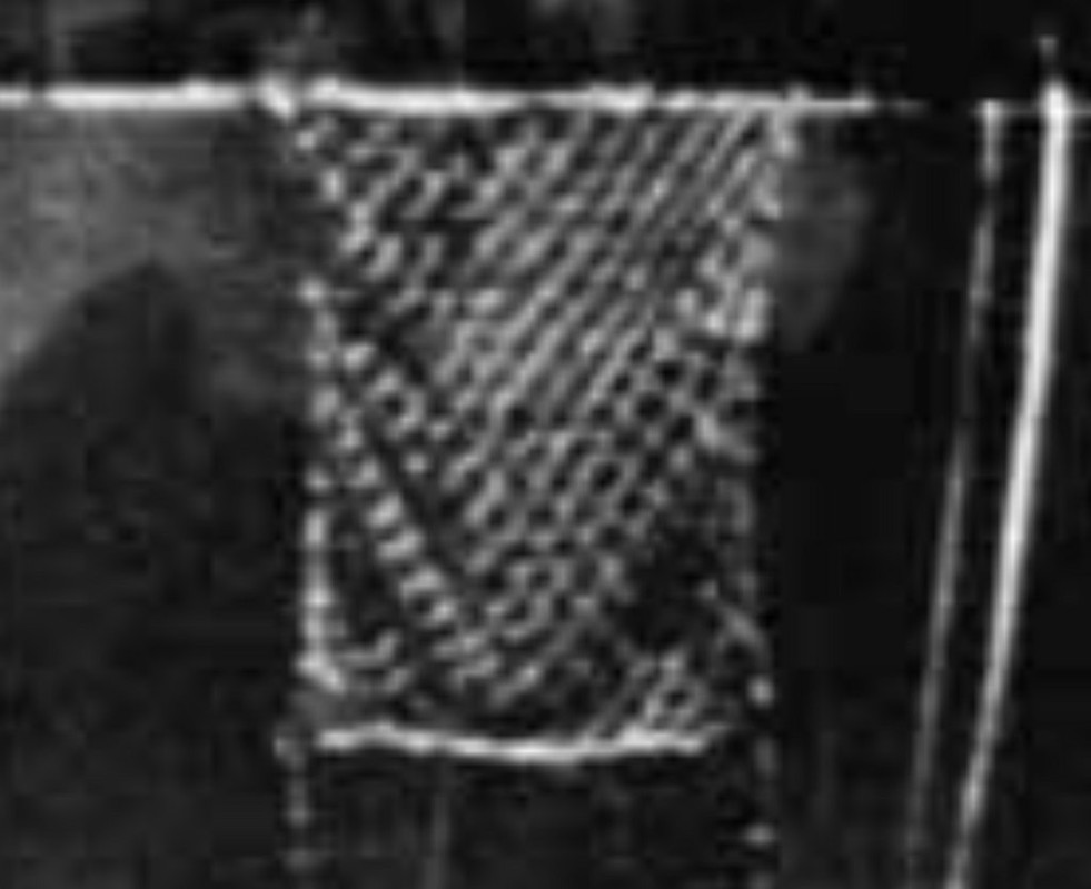
As you can see, there were ONLY 3 "BI" IFF systems made and it isn't clear to me which ships received this system. A document dated 30 January 1942, mentions several interesting details. The BE/BF set(s) had TWO antennas; a "mattress/curtain" type (CG66AAD) and a "Yagi" type (CG66AAB). (These two types of antennas can be seen in the above photo) Another paragraph notes that "One model BE/BF equipment, complete with Yagi antenna (was delivered) to USS HORNET."

From a list of equipments in each of the IFF systems on order from 1 October 1941, it is clear that BE/BF systems (transmitter and receiver) were utilized as one system and that BE (transmitter) system could use either the Curtain (CG66AAD) or Yagi (CG66AAB) type antennas, while the BF (receiver) system used the Yagi (CG66AAB) antenna. The BI system used the CG66AAM antenna. I still have no idea of what this antenna looks like

I believe that Tracy White had found a report of the IFF installation on USS HORNET in her Departure Report at Norfolk Navy Yard and that when USS HORNET went to the Pacific, she carried new IFF sets for the other carriers.

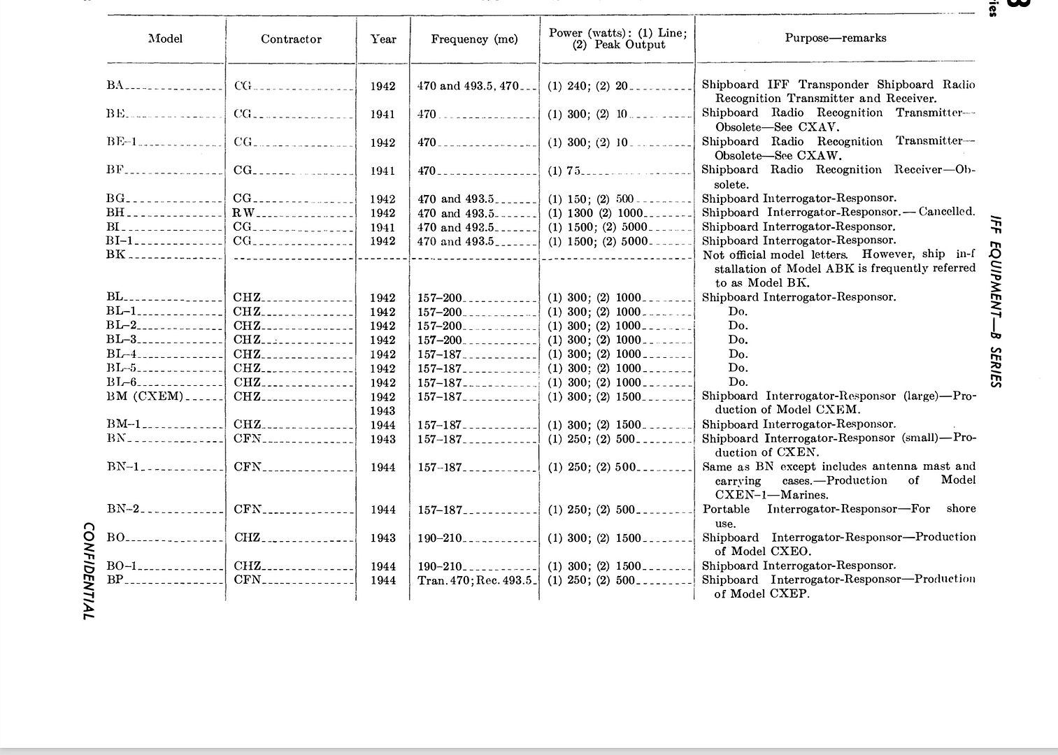
As a reference of the early IFF systems, here is a listing in a document from 1945 listing the various IFF equipments used (or had been used) by the USN ...

Image

I have a document of USN antennas created in the early 1960's, these antennas are listed, but no particulars like size or description are given nor are images shown.
User avatar
MartinJQuinn
Posts: 8506
Joined: Tue Jan 11, 2005 1:40 pm
Location: New Jersey

Re: Calling all USS Hornet CV-8 fans

Post by MartinJQuinn »

Thanks Ian. That's the clearest look I've seen of that area.

Rick - thanks for the info. The location of the smaller antenna is a head scratcher, as it would only be able to transmit in receive in a limited arc. At this point, no one can tell me what I've fabricated is right or wrong!
Martin

"Tomorrow is the most important thing in life. Comes into us at midnight very clean. It's perfect when it arrives and it puts itself in our hands. It hopes we've learned something from yesterday." John Wayne

Ship Model Gallery
Rick E Davis
Posts: 3871
Joined: Thu May 29, 2008 8:02 pm

Re: Calling all USS Hornet CV-8 fans

Post by Rick E Davis »

Martin, I can't answer your question directly, but somewhere in the back of my mind I thought they had two of these Yagi antennas, which as you can see are hard to see. The problems with line of sight and correlating these separate antennas from the search radars, was why the USN went with colocating the search and fire control antennas with the IFF antenna. In the early periods with the FD radar and SC/SC-1 search radars on destroyers (and other ships), the IFF function was handled via the BL "stovepipe" antenna which was omnidirectional and less than precise on which aircraft was a friend and not.
User avatar
Dick J
Posts: 1990
Joined: Mon Aug 06, 2007 6:29 pm

Re: Calling all USS Hornet CV-8 fans

Post by Dick J »

I don't know what Tracy found on Hornet, but he found the departure report for Yorktown which documented installation of her BI set. The early sets were experimental, and so were installed wherever they could fit without structural changes. Those structural changes would only be made for permanent installation of "proven" hardware.
Rick E Davis
Posts: 3871
Joined: Thu May 29, 2008 8:02 pm

Re: Calling all USS Hornet CV-8 fans

Post by Rick E Davis »

Dick, I stand corrected about the Departure Report was for USS YORKTOWN, not USS HORNET. It has been awhile since we discussed the IFF system installs on the early carriers. I couldn't remember where this subject was discussed and relied on my failing memory. :scratch:

True that the early IFF sets were experimental, but they were an operational system in any case. The early SC and FD radars were really still experimental as well. The first of the SC and FD radar systems installed on a destroyer was in September 1941, by NRL and contractor engineers at the Washington Navy Yard. I'm still amazed that the first "production (in fact still experimental)" radars were installed in December 1941 onboard the destroyer USS ROE (DD-418) and that the improved and more powerful SC-1 radar was available in about March-April 1942 for installation aboard ships. The reliability of these early systems was really very poor. Also, as more "electronic" microwave emitters (radar, IFF, comm) were added aboard USN ships, the USN had to learn how to adequately place these systems onboard ships for the best performance and non interference.
Last edited by Rick E Davis on Thu Nov 12, 2020 12:05 am, edited 1 time in total.
User avatar
MartinJQuinn
Posts: 8506
Joined: Tue Jan 11, 2005 1:40 pm
Location: New Jersey

Re: Calling all USS Hornet CV-8 fans

Post by MartinJQuinn »

I improvised. No one can tell me I'm wrong (of course, now a picture will show up)
HornetIsland.jpg
Martin

"Tomorrow is the most important thing in life. Comes into us at midnight very clean. It's perfect when it arrives and it puts itself in our hands. It hopes we've learned something from yesterday." John Wayne

Ship Model Gallery
Rick E Davis
Posts: 3871
Joined: Thu May 29, 2008 8:02 pm

Re: Calling all USS Hornet CV-8 fans

Post by Rick E Davis »

Martin,

You don't have to change anything if you don't want to. As you say, not many people will know the difference. But, the antenna you have made before the Mk 37 director isn't a Yagi type antenna. Look at the image that Ian posted and it is clear that the antenna before the Mk 37 director is a Yagi type. The antenna in the foremast, is a mattress/curtain type antenna. Without getting into antenna theory, "Mattress/Curtain" type antennas, like SC, CXAM, etc can be called "vertical arrays" that use multiple dipoles to get more power gain with a reflector screen. Yagi antennas, use "horizontal arrays" stacked in series and maybe also in parallel to get more gain. Yagi antennas were seen on a lot of USN aircraft during WWII. They were more compact and feasible on an aircraft platform. A common type of Yagi antennas seen today are for use as TV and radio antennas.

How then Yagi antennas have many different designs. Below are some types and callouts as to what various parts of them are for.
yagi_antenna_1.jpg
yagi_antenna_1.jpg (9.29 KiB) Viewed 9593 times
yagi-uda-diagram.jpg
jd_Yagi_antenna_Minitrack.jpg
Like everyone else, I can't tell from the Ian image what the whole antenna looks like, but it looks like it is a wide Yagi with maybe two or three parallel arrays. What the separate dipole at the top is for, I don't know. For reference, I have copied Ian's image and reposted it here.
CV-8%20BI%20installation.jpg
You could for all practical purposes, rotate your antenna down 90-degrees and approximate the antenna as it appears in the image. Of course many will say "Hey Martin, your antenna fell over!" :big_grin:
User avatar
MartinJQuinn
Posts: 8506
Joined: Tue Jan 11, 2005 1:40 pm
Location: New Jersey

Re: Calling all USS Hornet CV-8 fans

Post by MartinJQuinn »

DavidP wrote:Rick, if he has been drinking then of course it fell over.
That is a distinct possibility.

Thanks Rick. In some of the photos of Hornet, it does look like that antenna is in the position I put it in. At this point, I'm going to leave it and dare someone to prove me wrong! :)
Martin

"Tomorrow is the most important thing in life. Comes into us at midnight very clean. It's perfect when it arrives and it puts itself in our hands. It hopes we've learned something from yesterday." John Wayne

Ship Model Gallery
Ian Roberts
Posts: 314
Joined: Sun Jan 08, 2012 4:59 pm
Location: Austin
Contact:

Re: Calling all USS Hornet CV-8 fans

Post by Ian Roberts »

Here's another view of the reflector forward of the Mark 37 director:
CV-8 BI installation 2.jpg
Again, to my eyes this reflector looks identical to the one mounted on the foremast. My guess for this antenna is that it was elevated to aim straight up to clear space for work on that deck, but as always that's a guess.

Martin - your model is looking fantastic!
User avatar
MartinJQuinn
Posts: 8506
Joined: Tue Jan 11, 2005 1:40 pm
Location: New Jersey

Re: Calling all USS Hornet CV-8 fans

Post by MartinJQuinn »

Thanks Ian - for the photo and for the comments. Much appreciated. I agree, I think it's turn up for the moment.
Martin

"Tomorrow is the most important thing in life. Comes into us at midnight very clean. It's perfect when it arrives and it puts itself in our hands. It hopes we've learned something from yesterday." John Wayne

Ship Model Gallery
Post Reply

Return to “Aircraft Carriers”