Tom,
The pulley assy. looks great! Good job on that!!
Hank
APA project
Moderators: MartinJQuinn, JIM BAUMANN, HMAS, Tiny69, Dave Wooley
-
BB62vet

- Posts: 3161
- Joined: Mon Nov 18, 2013 3:41 pm
- Location: Mocksville, NC
Re: APA project
HMS III
Mocksville, NC
BB62 vet 68-69
Builder's yard:
USS STODDARD (DD-566) 66-68 1:144, Various Lg Scale FC Directors
Finished:
USS NEW JERSEY (BB-62) 67-69 1:200
USN Sloop/Ship PEACOCK (1813) 1:48
ROYAL CAROLINE (1748) 1:47
AVS (1768) 1:48
Mocksville, NC
BB62 vet 68-69
Builder's yard:
USS STODDARD (DD-566) 66-68 1:144, Various Lg Scale FC Directors
Finished:
USS NEW JERSEY (BB-62) 67-69 1:200
USN Sloop/Ship PEACOCK (1813) 1:48
ROYAL CAROLINE (1748) 1:47
AVS (1768) 1:48
-
Fliger747
- Posts: 5068
- Joined: Wed Jan 02, 2013 1:15 am
Re: APA project
Thanks Hank:
The second iteration I just printed are very slightly larger and do have the full loose articulation. The chain was flop, so needs some more work. Making some with rings at both ends as well.
Cheers: Tom
The second iteration I just printed are very slightly larger and do have the full loose articulation. The chain was flop, so needs some more work. Making some with rings at both ends as well.
Cheers: Tom
-
Fliger747
- Posts: 5068
- Joined: Wed Jan 02, 2013 1:15 am
Re: APA project
Cheers: Tom
-
BB62vet
- Posts: 3161
- Joined: Mon Nov 18, 2013 3:41 pm
- Location: Mocksville, NC
Re: APA project
Tom,
Your pulleys look excellent! I think you've really got the hang of this. How do you do a separate ring within another?
Hank
Your pulleys look excellent! I think you've really got the hang of this. How do you do a separate ring within another?
Hank
HMS III
Mocksville, NC
BB62 vet 68-69
Builder's yard:
USS STODDARD (DD-566) 66-68 1:144, Various Lg Scale FC Directors
Finished:
USS NEW JERSEY (BB-62) 67-69 1:200
USN Sloop/Ship PEACOCK (1813) 1:48
ROYAL CAROLINE (1748) 1:47
AVS (1768) 1:48
Mocksville, NC
BB62 vet 68-69
Builder's yard:
USS STODDARD (DD-566) 66-68 1:144, Various Lg Scale FC Directors
Finished:
USS NEW JERSEY (BB-62) 67-69 1:200
USN Sloop/Ship PEACOCK (1813) 1:48
ROYAL CAROLINE (1748) 1:47
AVS (1768) 1:48
-
Fliger747
- Posts: 5068
- Joined: Wed Jan 02, 2013 1:15 am
Re: APA project
Hank:
Thank you! Designing loose overlapping objects isn't hard, but there is some variation in printing. Take two rings, oriented at right angles, unlike real items, virtual ones can be moved right through one another. Along as they are not touching when they are printed, they should remain free. The issue comes with having enough clearance, as there is a tendency for the items to grow together during printing.
Cheers: Tom
Thank you! Designing loose overlapping objects isn't hard, but there is some variation in printing. Take two rings, oriented at right angles, unlike real items, virtual ones can be moved right through one another. Along as they are not touching when they are printed, they should remain free. The issue comes with having enough clearance, as there is a tendency for the items to grow together during printing.
Cheers: Tom
-
Fliger747
- Posts: 5068
- Joined: Wed Jan 02, 2013 1:15 am
Re: APA project
Today printing a rudder and sternpost, says 11 hours as I am printing it upright. We will see how that goes.
Also designed a 3D prop, my first attempt. I like my brass one I made, though one could possibly do this is a wax resin and do a lost wax casting in Bronze. Perhaps some jeweler would have the capability to do the actual casting?
Also designed a 3D prop, my first attempt. I like my brass one I made, though one could possibly do this is a wax resin and do a lost wax casting in Bronze. Perhaps some jeweler would have the capability to do the actual casting?
-
DrPR

- Posts: 1689
- Joined: Sun Mar 07, 2010 12:01 am
- Location: Corvallis, Oregon, USA
- Contact:
Re: APA project
Tom,
I really appreciate all the research and detail you are putting into this model. It is excellent!
I see you are working on a CAD model of the propeller. Been there, done that! It was one of the hardest parts of the ship to model using the CAD program I have. My model still needs some improvement.
The real things were mind boggling! The propeller was over 12 feet (3.66 meters) diameter with proportional pitch blades that were only a fraction of an inch thick near the tips, with 1/16 inch (1.59 mm) radius edges. The rough bronze casting weighed 15906 pounds (7205 kilograms). It was then bored to fit a tapered propeller shaft and the surface was machined to +/- 1/32 inch (0.79 mm) tolerance and dynamically balanced for 350 RPM. Finish machining removed 1311 pounds (2894 kilograms)!
The propeller struts were even more impressive - 12 foot struts with a 6 foot long x 2.5 foot diameter (1.8 x 0.76 meters) hub, all cast in one piece and then bored in place on the ship to take the propeller shaft and bearings with the struts machined to an airfoil cross section!
The blueprints give exact instructions for making these things. It is very interesting reading! And these were just for a light cruiser - think of the size of the props for a carrier or battleship!
I would love to have been able to visit the shipyards and watch these things being made!
I did watch some shipyard heavy work in Yokosuka and that was amazing, but not nearly as big as the propellers!
Phil
I really appreciate all the research and detail you are putting into this model. It is excellent!
I see you are working on a CAD model of the propeller. Been there, done that! It was one of the hardest parts of the ship to model using the CAD program I have. My model still needs some improvement.
The real things were mind boggling! The propeller was over 12 feet (3.66 meters) diameter with proportional pitch blades that were only a fraction of an inch thick near the tips, with 1/16 inch (1.59 mm) radius edges. The rough bronze casting weighed 15906 pounds (7205 kilograms). It was then bored to fit a tapered propeller shaft and the surface was machined to +/- 1/32 inch (0.79 mm) tolerance and dynamically balanced for 350 RPM. Finish machining removed 1311 pounds (2894 kilograms)!
The propeller struts were even more impressive - 12 foot struts with a 6 foot long x 2.5 foot diameter (1.8 x 0.76 meters) hub, all cast in one piece and then bored in place on the ship to take the propeller shaft and bearings with the struts machined to an airfoil cross section!
The blueprints give exact instructions for making these things. It is very interesting reading! And these were just for a light cruiser - think of the size of the props for a carrier or battleship!
I would love to have been able to visit the shipyards and watch these things being made!
I did watch some shipyard heavy work in Yokosuka and that was amazing, but not nearly as big as the propellers!
Phil
- Attachments
-
A collision at sea will ruin your entire day. Aristotle
-
Fliger747
- Posts: 5068
- Joined: Wed Jan 02, 2013 1:15 am
Re: APA project
As can be seen, my effort is very rudimentary. I do have the actual dimensions and contours for the APA propeller. Of course a ship's propeller has an appropriate "airfoil section" adjusted for the appropriate Reynold's Number. Apparently for submarines very exacting machining is required to reduce cavitation and noise making. the Russian's via their spy networks were able to acquire ut technology which has greatly reduced the propeller noise profile.
It would not be possible to achieve the propeller you show by working brass blades out of two dimensions into the required compound curves and thicknesses. Perhaps one could form brass bladed over a form. I pitched mine by hand, not an optimal solution. The answer is more in the way of the way the real ones are produced, a casting with some (more minor) surface finish. Apparently there is a wax resin 3 D printing that could be used for a lost wax casting procedure. Perhaps you remember those Japanese brass HO locomotives that were popular in the 60's including a lot of lost wax detail parts. There are jewelers and other artisans which might be able to effect such a casting?
On the waterfront in Bremerton, near the Turner Joy, there is (I believe) a Destroyer Propeller. Very impressive. Those had to absorb perhaps 30,000 hp , not a lot less per shaft than a four shafted cruiser. Do you know what RPM your ship made at flank speed? My recollection was that Missouri made maybe 230 RPM at top speed?
By comparison the single four bladed prop of the APA was a snitch under 20' in diameter. Pitched very differently for general service in the 10-15 knot range. Especially for use with the commonly available Uniflow triple expansion engines with no reduction gears, such props were big slow turners.
The bigger the scale of the model, the more fidelity is required (and possible).
Cheers: Tom
It would not be possible to achieve the propeller you show by working brass blades out of two dimensions into the required compound curves and thicknesses. Perhaps one could form brass bladed over a form. I pitched mine by hand, not an optimal solution. The answer is more in the way of the way the real ones are produced, a casting with some (more minor) surface finish. Apparently there is a wax resin 3 D printing that could be used for a lost wax casting procedure. Perhaps you remember those Japanese brass HO locomotives that were popular in the 60's including a lot of lost wax detail parts. There are jewelers and other artisans which might be able to effect such a casting?
On the waterfront in Bremerton, near the Turner Joy, there is (I believe) a Destroyer Propeller. Very impressive. Those had to absorb perhaps 30,000 hp , not a lot less per shaft than a four shafted cruiser. Do you know what RPM your ship made at flank speed? My recollection was that Missouri made maybe 230 RPM at top speed?
By comparison the single four bladed prop of the APA was a snitch under 20' in diameter. Pitched very differently for general service in the 10-15 knot range. Especially for use with the commonly available Uniflow triple expansion engines with no reduction gears, such props were big slow turners.
The bigger the scale of the model, the more fidelity is required (and possible).
Cheers: Tom
-
Iceman 29

- Posts: 1945
- Joined: Tue Sep 29, 2020 4:35 pm
- Location: Bretagne, France
Re: APA project
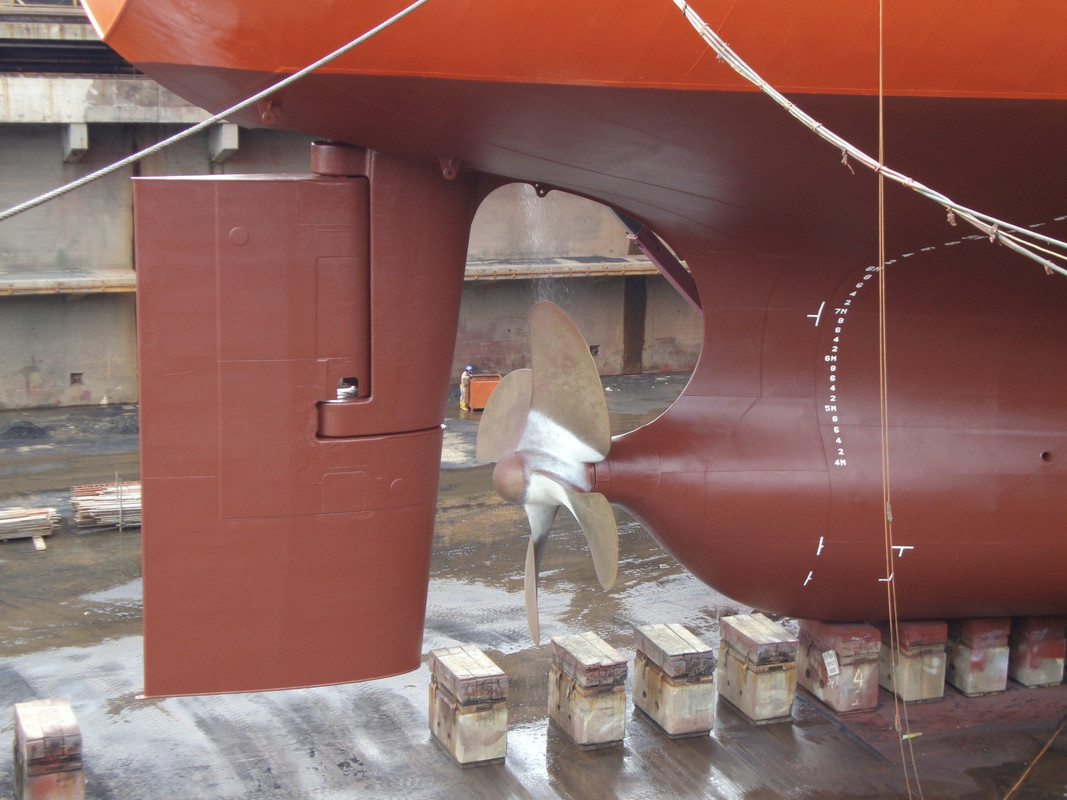
The slower the shaft line rotates at full power, the larger the diameter of the propeller.
Large cargo ships are usually equipped with slow 2-stroke diesel engines at the moment, the reversible engine is directly connected to the shaft line and runs at a speed between 90 revolutions per minute on a 90000 hp engine and 115 on a 22000 hp Sulzer engine.
Here are some personal photos of a liquefied gas transport of 225 meters and 22000 hp, speed 18 knots.
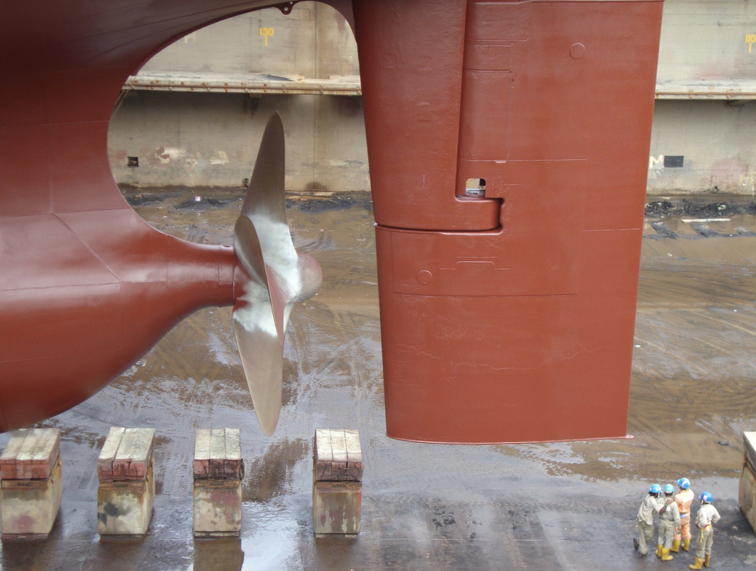
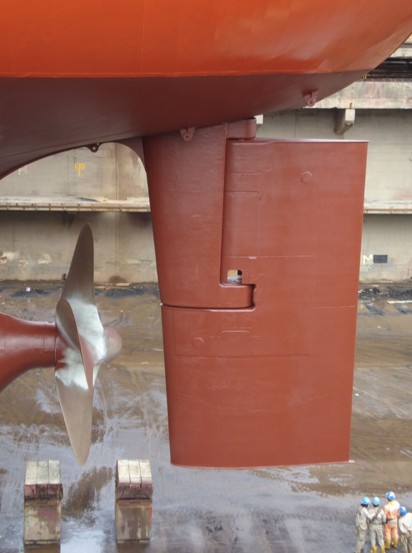
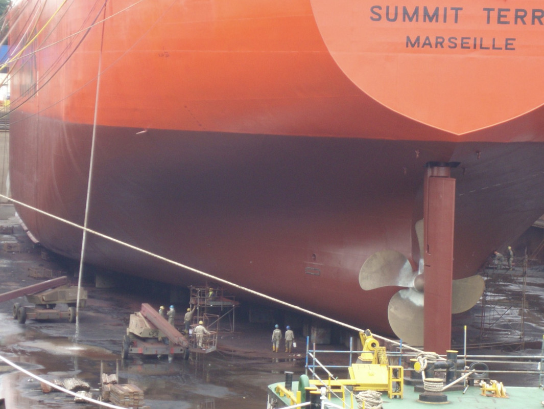
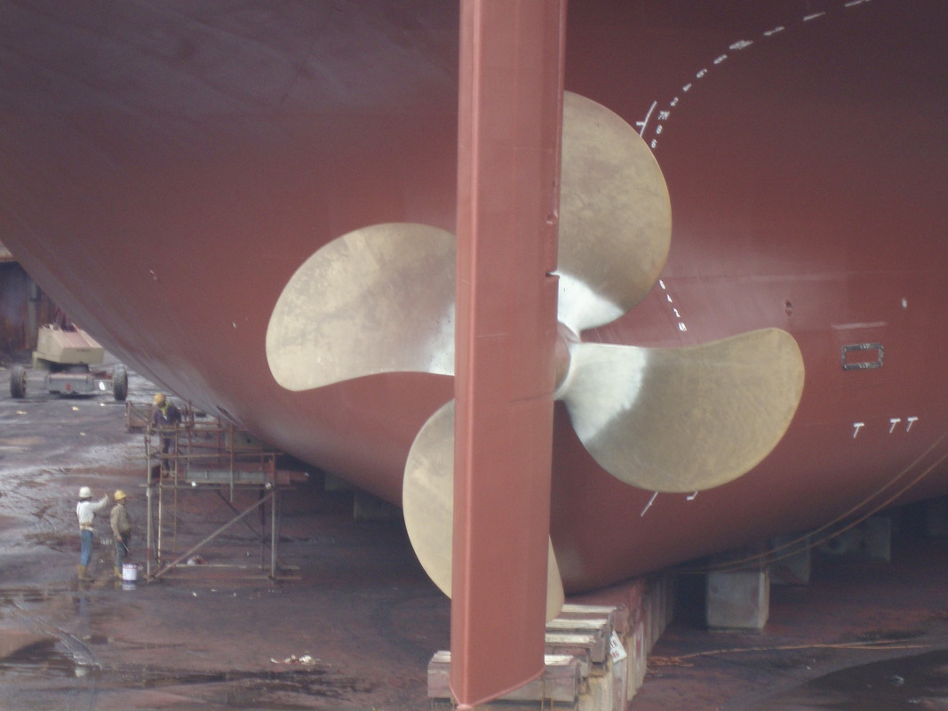
Large cargo ships are usually equipped with slow 2-stroke diesel engines at the moment, the reversible engine is directly connected to the shaft line and runs at a speed between 90 revolutions per minute on a 90000 hp engine and 115 on a 22000 hp Sulzer engine.
Here are some personal photos of a liquefied gas transport of 225 meters and 22000 hp, speed 18 knots.
Pascal
�Battleship Bretagne 3D: https://vu.fr/FvCY
�SS Delphine 3D: https://vu.fr/NeuO
�SS Nomadic 3D: https://vu.fr/tAyL
�USS Nokomis 3D: https://vu.fr/kntC
�USS Pamanset 3D: https://vu.fr/jXGQ
�Battleship Bretagne 3D: https://vu.fr/FvCY
�SS Delphine 3D: https://vu.fr/NeuO
�SS Nomadic 3D: https://vu.fr/tAyL
�USS Nokomis 3D: https://vu.fr/kntC
�USS Pamanset 3D: https://vu.fr/jXGQ
-
Fliger747
- Posts: 5068
- Joined: Wed Jan 02, 2013 1:15 am
Re: APA project
Interesting how much the propellers have changed from the WWII, with I am sure a great increase in efficiency! The ship above has a beautiful counterbalanced rudder, much like those found on an Iowa class battleship. In aircraft a similar relation is found between optimal speed of rotation and diameter. The culprit in aircraft is the speed of sound for the tips which causes a great loss of efficiency. Water not being compressible has slightly different dynamics, cavitation being an adverse effect. Flying the Pacific many hundreds of times, it was very common to see the large modern cargo ships "steaming" along at 20 knots or more with great efficiency!
-
Fliger747
- Posts: 5068
- Joined: Wed Jan 02, 2013 1:15 am
Re: APA project
On the APA the prop was bolted to the shaft such that it could be unbolted and removed without removing the rudder and stern post. For this reason it did not have a streamlined "tailcone". Though I could have turned the brass tail cone on my lathe the straight central hub made things easier.
Cheers: Tom
-
BB62vet
- Posts: 3161
- Joined: Mon Nov 18, 2013 3:41 pm
- Location: Mocksville, NC
Re: APA project
Tom,
Looking really good!!! Very interesting how the program decides where to put support legs.
Hank
Looking really good!!! Very interesting how the program decides where to put support legs.
Hank
HMS III
Mocksville, NC
BB62 vet 68-69
Builder's yard:
USS STODDARD (DD-566) 66-68 1:144, Various Lg Scale FC Directors
Finished:
USS NEW JERSEY (BB-62) 67-69 1:200
USN Sloop/Ship PEACOCK (1813) 1:48
ROYAL CAROLINE (1748) 1:47
AVS (1768) 1:48
Mocksville, NC
BB62 vet 68-69
Builder's yard:
USS STODDARD (DD-566) 66-68 1:144, Various Lg Scale FC Directors
Finished:
USS NEW JERSEY (BB-62) 67-69 1:200
USN Sloop/Ship PEACOCK (1813) 1:48
ROYAL CAROLINE (1748) 1:47
AVS (1768) 1:48
-
Fliger747
- Posts: 5068
- Joined: Wed Jan 02, 2013 1:15 am
Re: APA project
Hank:
My fault to some extent, there is a feature that allows you to see how every layer will print by moving a slider. If I had gone through this step then I should have seen the small support going through the bearing hole.
Today I painted (in a lighter Haze Gray) some MK 141 launchers and Harpoon armored boxes I had printed a couple of weeks ago to replace the cast ones I had made. Also printed a few more small 1:200 pieces to sprinkle about Missouri and Alaska.
Cheers: Tom
My fault to some extent, there is a feature that allows you to see how every layer will print by moving a slider. If I had gone through this step then I should have seen the small support going through the bearing hole.
Today I painted (in a lighter Haze Gray) some MK 141 launchers and Harpoon armored boxes I had printed a couple of weeks ago to replace the cast ones I had made. Also printed a few more small 1:200 pieces to sprinkle about Missouri and Alaska.
Cheers: Tom
-
BB62vet
- Posts: 3161
- Joined: Mon Nov 18, 2013 3:41 pm
- Location: Mocksville, NC
Re: APA project
Tom,Fliger747 wrote:Hank:
My fault to some extent, there is a feature that allows you to see how every layer will print by moving a slider. If I had gone through this step then I should have seen the small support going through the bearing hole.
Today I painted (in a lighter Haze Gray) some MK 141 launchers and Harpoon armored boxes I had printed a couple of weeks ago to replace the cast ones I had made. Also printed a few more small 1:200 pieces to sprinkle about Missouri and Alaska.
Cheers: Tom
I'll assume this is in ChituBox, right? I wasn't aware of any of that sort of backchecking, etc.
Hank
HMS III
Mocksville, NC
BB62 vet 68-69
Builder's yard:
USS STODDARD (DD-566) 66-68 1:144, Various Lg Scale FC Directors
Finished:
USS NEW JERSEY (BB-62) 67-69 1:200
USN Sloop/Ship PEACOCK (1813) 1:48
ROYAL CAROLINE (1748) 1:47
AVS (1768) 1:48
Mocksville, NC
BB62 vet 68-69
Builder's yard:
USS STODDARD (DD-566) 66-68 1:144, Various Lg Scale FC Directors
Finished:
USS NEW JERSEY (BB-62) 67-69 1:200
USN Sloop/Ship PEACOCK (1813) 1:48
ROYAL CAROLINE (1748) 1:47
AVS (1768) 1:48
-
Fliger747
- Posts: 5068
- Joined: Wed Jan 02, 2013 1:15 am
Re: APA project
On the right side of the display is a vertical slider. This can run automatically and show the slicing, layer by layer, or you can manually move it.
: )
: )
-
DrPR
- Posts: 1689
- Joined: Sun Mar 07, 2010 12:01 am
- Location: Corvallis, Oregon, USA
- Contact:
Re: APA project
Tom,
The Clevelands had four 25,000 HP turbines and reducing gear. The four propellers were all different. Two were right handed and two were left handed. The outboard props were positioned a bit higher than the inboard props, where the water density was lower, so they generated a bit less thrust per unit surface area. In addition, the inboard props were located inside the curvature of the lower hull where water was channeled around them. The outboard props were on an outside curve of the hull with more free flowing water, and this also generated a bit less thrust. So the outboard blades had a few percent larger surface area to generate the same thrust at the same RPM.
The propellers turned about 10 RPM per knot, but it wasn't a perfectly linear relationship. They were balanced for 350 RPM but our top speed was about 33 knots. At that speed the prop shafts vibrated quite a bit. My warhead magazine was between the inboard shafts and at high speeds anything lying on the deck bounced around. I suspect they made enough noise that a submarine could hear them many miles away!
I have taken lost wax casting classes and I have a friend who is very skilled at metal castings. It really isn't possible to cast perfectly scale propellers at 1:96 like the one shown, not even with rotating molds. The actual blades were about 2 inches (5 cm) thick near the base, tapering to 1/16 (1.5 mm) at the tips and edges. At 1:96 that would be 0.020 inch (0.52 mm) at the base to 0.00065 inch (0.016 mm) at the tips. For comparison, a sheet of ordinary printer paper is about 0.003 inch (0.08 mm) thick. The propeller blade would vary from about the thickness of six sheets of paper at the base to 1/4 the thickness of a sheet of paper at the tips and edges.
Phil
The Clevelands had four 25,000 HP turbines and reducing gear. The four propellers were all different. Two were right handed and two were left handed. The outboard props were positioned a bit higher than the inboard props, where the water density was lower, so they generated a bit less thrust per unit surface area. In addition, the inboard props were located inside the curvature of the lower hull where water was channeled around them. The outboard props were on an outside curve of the hull with more free flowing water, and this also generated a bit less thrust. So the outboard blades had a few percent larger surface area to generate the same thrust at the same RPM.
The propellers turned about 10 RPM per knot, but it wasn't a perfectly linear relationship. They were balanced for 350 RPM but our top speed was about 33 knots. At that speed the prop shafts vibrated quite a bit. My warhead magazine was between the inboard shafts and at high speeds anything lying on the deck bounced around. I suspect they made enough noise that a submarine could hear them many miles away!
I have taken lost wax casting classes and I have a friend who is very skilled at metal castings. It really isn't possible to cast perfectly scale propellers at 1:96 like the one shown, not even with rotating molds. The actual blades were about 2 inches (5 cm) thick near the base, tapering to 1/16 (1.5 mm) at the tips and edges. At 1:96 that would be 0.020 inch (0.52 mm) at the base to 0.00065 inch (0.016 mm) at the tips. For comparison, a sheet of ordinary printer paper is about 0.003 inch (0.08 mm) thick. The propeller blade would vary from about the thickness of six sheets of paper at the base to 1/4 the thickness of a sheet of paper at the tips and edges.
Phil
A collision at sea will ruin your entire day. Aristotle
-
Fliger747
- Posts: 5068
- Joined: Wed Jan 02, 2013 1:15 am
Re: APA project
The WWII fast battleships had a great deal of trouble with propeller fittings. Both a combination of left and right handed propellers as well as both 4 an 5 blade units were adopted on the inboard and outboard shafts. At certain speeds the optical rangefinders were hardy useable. Several ships had extra bracing added to the aft fire control director towers.
Certainly one may have to compromise a little on exact scale, particularly if yours is to be an operating model? Model airplane propellers are not exact duplicates of the full size counterparts due to the huge difference in the Reynolds number in which the operate. Ships likewise, model or full scale behave very differently because of their size difference and the wave making properties of water. In the controlled and instrumented towing tests in the David Taylor model basin, appropriate "fudge factors" (derived scaling parameters). For the WWII USN wartime cruisers actual trial performance speed tended to be a little less than forecast. I am not sure how they did the turning testing, but Alaska is often denigrated for poor tactical radius on the basis of the model basin tests, but in actual service was on par with an Iowa and better than a Fletcher.
Maybe one could make a two piece form to compound form fairly thin brass blades and silver slider or braze them on. Mine are formed by hand, which isn't very precise.
Good luck!
Certainly one may have to compromise a little on exact scale, particularly if yours is to be an operating model? Model airplane propellers are not exact duplicates of the full size counterparts due to the huge difference in the Reynolds number in which the operate. Ships likewise, model or full scale behave very differently because of their size difference and the wave making properties of water. In the controlled and instrumented towing tests in the David Taylor model basin, appropriate "fudge factors" (derived scaling parameters). For the WWII USN wartime cruisers actual trial performance speed tended to be a little less than forecast. I am not sure how they did the turning testing, but Alaska is often denigrated for poor tactical radius on the basis of the model basin tests, but in actual service was on par with an Iowa and better than a Fletcher.
Maybe one could make a two piece form to compound form fairly thin brass blades and silver slider or braze them on. Mine are formed by hand, which isn't very precise.
Good luck!
-
Fliger747
- Posts: 5068
- Joined: Wed Jan 02, 2013 1:15 am
Re: APA project
This was printed vertically and came out fine, taking some 11 hours to print!
Cheers: Tom
-
BB62vet
- Posts: 3161
- Joined: Mon Nov 18, 2013 3:41 pm
- Location: Mocksville, NC
Re: APA project
Tom,
Looks perfect to me. I think the paint scheme would be correct due to your research. Kudo!
Hank
Looks perfect to me. I think the paint scheme would be correct due to your research. Kudo!
Hank
HMS III
Mocksville, NC
BB62 vet 68-69
Builder's yard:
USS STODDARD (DD-566) 66-68 1:144, Various Lg Scale FC Directors
Finished:
USS NEW JERSEY (BB-62) 67-69 1:200
USN Sloop/Ship PEACOCK (1813) 1:48
ROYAL CAROLINE (1748) 1:47
AVS (1768) 1:48
Mocksville, NC
BB62 vet 68-69
Builder's yard:
USS STODDARD (DD-566) 66-68 1:144, Various Lg Scale FC Directors
Finished:
USS NEW JERSEY (BB-62) 67-69 1:200
USN Sloop/Ship PEACOCK (1813) 1:48
ROYAL CAROLINE (1748) 1:47
AVS (1768) 1:48
-
Fliger747
- Posts: 5068
- Joined: Wed Jan 02, 2013 1:15 am
Re: APA project
Today I fitted the rudder and post and added a grab rail to the top of the clipping shack on the 03 level. as it turns out extra printed rail material when trained height wise provides endless amounts of hand rail material. Re rigging some of the aft cargo gear I damaged , some very minor repairs to make around the #1 hatch as well.
It other tasks I designed and printed some Mk52 AA directors with radar dishes (1:192 for Alaska). They may require some minor size alteration. Anybody have scaled drawings of this units?
I finally ordered the plans for the ARL project though that's a long ways down the road. With the basic dimensions I can build the detail from photos in my dad's cruise scrapbook. Those original photos are a wonderful detail reference.
Cheers: Tom
It other tasks I designed and printed some Mk52 AA directors with radar dishes (1:192 for Alaska). They may require some minor size alteration. Anybody have scaled drawings of this units?
I finally ordered the plans for the ARL project though that's a long ways down the road. With the basic dimensions I can build the detail from photos in my dad's cruise scrapbook. Those original photos are a wonderful detail reference.
Cheers: Tom