Marijn,
I'm in awe.... Your brass modelling skills surpass everything you do in plastic!
HMS Victory and Le Redoutable at Trafalgar (1/300)
Moderators: BB62vet, MartinJQuinn, JIM BAUMANN, Jon, Dan K
-
Maarten Sch�nfeld

- Posts: 1842
- Joined: Fri Dec 12, 2008 12:44 pm
- Location: Herk-de-Stad, Belgium
Re: HMS Victory and Le Redoutable at Trafalgar (1/300)
"I've heard there's a wicked war a-blazing, and the taste of war I know so very well
Even now I see the foreign flag a-raising, their guns on fire as we sail into hell"
Roger Whittaker +9/13/2023
Even now I see the foreign flag a-raising, their guns on fire as we sail into hell"
Roger Whittaker +9/13/2023
-
wefalck

- Posts: 2112
- Joined: Wed Sep 28, 2011 12:04 pm
- Location: Paris
- Contact:
Re: HMS Victory and Le Redoutable at Trafalgar (1/300)
Fantastic detail at this scale - as usual. I really admire your work with polystyrene sheet.
You should really try to get yourself a watchmakers lathe, if you are going to continue with such stuff. Much safer to use, because it has a tailstock and you can fashion yourself wooden steadies for filing. These lathes also come with so-called filing-rests and have an indexing ring in their main pulley, so that filing regular squares, hexagons or octgons is made very easy.
As a safety measure, I run all my machines from foot-switches, including the transformer for the hand-held drill. In this way you have both hands free for work and just lifting the foot stops the machine without having to look for the on-off switch.
BTW, what cement did you use for the styrene sheet/brass bonds ?
Just to mention: cross-drilling of 0.6 mm rod with say a 0.2 mm is quite possible, given the right equipment. Just did this last night - well actually 1 mm brass rod that then will be taper-turned down to 0.6 mm
Eberhard
Former chairman Arbeitskreis historischer Schiffbau e.V. (German Association for Shipbuilding History)
--------------------------------------------------------------------------------------------------------------------------------------------------------------------------------------------


Former chairman Arbeitskreis historischer Schiffbau e.V. (German Association for Shipbuilding History)
--------------------------------------------------------------------------------------------------------------------------------------------------------------------------------------------
-
maxim
- Posts: 3993
- Joined: Tue Jun 14, 2005 6:23 am
- Location: Bonn

-
marijn van gils
- Posts: 2697
- Joined: Tue Feb 06, 2007 10:24 am
- Location: Belgium
Re: HMS Victory and Le Redoutable at Trafalgar (1/300)
Many thansk everyone! 
And indexing ring would be very helpfull though. Now I had to position the piece by eye in the clamp, which is of course not so precise. Maybe something like exists that can be used without a late?
A milling machine would also work much more precisely for the square and hexagone sections. Maybe someday in the future...
But if a joint really needs some strenght, I glue with superglue directly. First gel superglue for easier positioning, then reinforcing with thin superglue.
If even more strength would be needed, I would use two-part epoxy, but I rarely need to.
(That's on my list though, but maybe I should immediately get a mill instead?)
Also, the upper (thick) end of the dolphin stryker is 0,6mm. The lower end, through which the stays would have to go, is only about 0,3mm...
Still possible of course, but again a bit more difficult...
Thanks for all the advices wefalck! Very interesting!
Many thanks Maarten! It is more time-consuming than plastic, and there is less room for error. Also, on plastic I can do fine stuff with the scalpel that is not possible on brass. But I find brass a very nice material to work with, and of course here I need it for its strength and stifness. But when I have the choice, I'll take styrene (like the mizzen mast)!Maarten Sch�nfeld wrote:Your brass modelling skills surpass everything you do in plastic!
I have tried turning on my Proxxon lathe, but the pieces are too long and thin, causing them to flex too much, even with the tailstock, and even with a fixed steady. A travelling steady might be a solution, buth then I would have to get the PD400 lathe instead of the PD250/E which costs about 1000 euro's more (and I'm not even sure a travelling steady would actually work well for this...). Maybe a watchmakers lathe would work better than the Proxxon, but turning long thin pieces with the Dremel works very well too, and it is quite easy and fast.wefalck wrote:You should really try to get yourself a watchmakers lathe, if you are going to continue with such stuff. Much safer to use, because it has a tailstock and you can fashion yourself wooden steadies for filing. These lathes also come with so-called filing-rests and have an indexing ring in their main pulley, so that filing regular squares, hexagons or octgons is made very easy.
And indexing ring would be very helpfull though. Now I had to position the piece by eye in the clamp, which is of course not so precise. Maybe something like exists that can be used without a late?
A milling machine would also work much more precisely for the square and hexagone sections. Maybe someday in the future...
That's a great tip! The Dremel Micro is quite handy, as my thumb naturaly rests on the on/off button while using it. But I 'll be getting myself a footswitch anyway...wefalck wrote:As a safety measure, I run all my machines from foot-switches, including the transformer for the hand-held drill. In this way you have both hands free for work and just lifting the foot stops the machine without having to look for the on-off switch.
I first meld the plastic to the brass with regular thin plastic glue (Tamiya super thin). This way, I have as much time to position the piece as I need, the plastic part conforms perfectly to the brass, and I have no added thickness from glue. But of course the bond is not very strong (I make sure to roughen the brass a bit though), so I reinforce the joint by running some thin superglue along it.wefalck wrote:YBTW, what cement did you use for the styrene sheet/brass bonds ?
But if a joint really needs some strenght, I glue with superglue directly. First gel superglue for easier positioning, then reinforcing with thin superglue.
If even more strength would be needed, I would use two-part epoxy, but I rarely need to.
That is true! But I don't have the right equipment. I don't even have a simple drill press...wefalck wrote:Just to mention: cross-drilling of 0.6 mm rod with say a 0.2 mm is quite possible, given the right equipment. Just did this last night - well actually 1 mm brass rod that then will be taper-turned down to 0.6 mm
(That's on my list though, but maybe I should immediately get a mill instead?)
Also, the upper (thick) end of the dolphin stryker is 0,6mm. The lower end, through which the stays would have to go, is only about 0,3mm...
Still possible of course, but again a bit more difficult...
Thanks for all the advices wefalck! Very interesting!
-
Martocticvs

- Posts: 239
- Joined: Tue Jan 26, 2016 7:59 am
- Contact:
Re: HMS Victory and Le Redoutable at Trafalgar (1/300)
Fantastic little masts! The extra-large matches make sense when you have gigantic hands, of course 
-
Dan K
- Posts: 9069
- Joined: Tue Jan 11, 2005 10:56 am
- Location: New York City
Re: HMS Victory and Le Redoutable at Trafalgar (1/300)
Since I've run out of superlatives, I'm just going to acknowledge your superior work, Marijn. Great learning curve.
Actually, I can go with "Bravo!"
Actually, I can go with "Bravo!"
-
MichelB

- Posts: 1689
- Joined: Tue Jan 11, 2005 10:26 am
- Location: The Netherlands
Re: HMS Victory and Le Redoutable at Trafalgar (1/300)
Allemachies... I've been away for two years, and you build ... *THIS*. Unbelievably gorgeous...
If all else fails, a complete pig-headed refusal to see facts in the face will see us through. - General Melchett
-
Neptune

- Posts: 2465
- Joined: Sun Mar 13, 2005 11:51 am
- Location: Belgium
Re: HMS Victory and Le Redoutable at Trafalgar (1/300)
Excellent job with the brass. Indeed with this kind of fine stuff, its strength definitely is a factor!
More curious to see the result with the rest of the ship instead of that giant hand though
More curious to see the result with the rest of the ship instead of that giant hand though
The merchant shipyard
-
Christian Bruer

- Posts: 574
- Joined: Tue Nov 21, 2006 7:44 am
- Location: Germany
- Contact:
Re: HMS Victory and Le Redoutable at Trafalgar (1/300)
Hello Marijn,
you made a most excellent progress in this inspiring and wonderful project.
I saw it life last in October 2019 at SMC and it would be a pleasure to see you and your inspiring project again in October this year.
Until then I will take a seat and be amazed by every new step you post here
you made a most excellent progress in this inspiring and wonderful project.
I saw it life last in October 2019 at SMC and it would be a pleasure to see you and your inspiring project again in October this year.
Until then I will take a seat and be amazed by every new step you post here
Cheers,
Christian
_________________
AKA "Painter"
VMF'06 - German Gamblers
Veritable Modelling Friends 2006, Germany
Christian
_________________
AKA "Painter"
VMF'06 - German Gamblers
Veritable Modelling Friends 2006, Germany
-
marijn van gils
- Posts: 2697
- Joined: Tue Feb 06, 2007 10:24 am
- Location: Belgium
Re: HMS Victory and Le Redoutable at Trafalgar (1/300)
Many thanks everyone! 
That will follow when I get the yards finished...

Neptune wrote:More curious to see the result with the rest of the ship instead of that giant hand though
I'm very much looking forward to seeing you and your new projects too Christian!Christian Bruer wrote:I saw it life last in October 2019 at SMC and it would be a pleasure to see you and your inspiring project again in October this year.
-
GewoonWouter

- Posts: 225
- Joined: Sat Mar 26, 2016 2:58 am
- Location: Belgium
Re: HMS Victory and Le Redoutable at Trafalgar (1/300)
The Giant Matchstick has returned!
I'm in awe again, what an impressing update again, this isn't modelling anymore, it's Art! Nice tip with the paper, that's something useful which I'll keep in mind.
I'm in awe again, what an impressing update again, this isn't modelling anymore, it's Art! Nice tip with the paper, that's something useful which I'll keep in mind.
-
JIM BAUMANN

- Posts: 5689
- Joined: Mon Jan 10, 2005 5:30 pm
- Location: Nr Southampton England
Re: HMS Victory and Le Redoutable at Trafalgar (1/300)
BEAUTIFUL ! what simply excellent and fine work !!
on the transition from square to round etc
BRAVO !
JB
on the transition from square to round etc
BRAVO !
JB
....I buy them at three times the speed I build 'em.... will I live long enough to empty my stash...?
http://www.modelshipgallery.com/gallery ... index.html
IPMS UK SIG (special interest group) www.finewaterline.com
http://www.modelshipgallery.com/gallery ... index.html
IPMS UK SIG (special interest group) www.finewaterline.com
-
Christian Bruer
- Posts: 574
- Joined: Tue Nov 21, 2006 7:44 am
- Location: Germany
- Contact:
Re: HMS Victory and Le Redoutable at Trafalgar (1/300)
Hello Marijn,marijn van gils wrote: Next, the head timbers and main rail were cut and carved from plastic sheet and installed. This was probably the most critical phase for getting all proportions and shapes to end up correct and symmetrical. The cross pieces were added in between the two main rails from stock square plastic rod.


I am amazed by all the different techniques you use and how you combine them
Regarding your excellent work on the rails and head timbers, I have a question about the method you had choosen to form them. Do you cut or bent the styrene struts for the head timbers and main rails? If you bent them, would you please explain the method you have used to bent them!?
I have the problem, that small styrene struts I bent with a round tool (like a drill), tend to went back straight once I add plastic glue.
TIA and all the best, Christian
Cheers,
Christian
_________________
AKA "Painter"
VMF'06 - German Gamblers
Veritable Modelling Friends 2006, Germany
Christian
_________________
AKA "Painter"
VMF'06 - German Gamblers
Veritable Modelling Friends 2006, Germany
-
wefalck
- Posts: 2112
- Joined: Wed Sep 28, 2011 12:04 pm
- Location: Paris
- Contact:
Re: HMS Victory and Le Redoutable at Trafalgar (1/300)
Tempering in a baking oven at 100�C or so may be the solution. The pieces will need to be fixed in the desired postion during tempering. A hot-air gun at low temperature may do the job as well. The idea is to relieve the stresses from bending, while keeping the part in shape during the process. It's like in injection moulding, but staying below the flow-temperature of the styrene.
Eberhard
Former chairman Arbeitskreis historischer Schiffbau e.V. (German Association for Shipbuilding History)
--------------------------------------------------------------------------------------------------------------------------------------------------------------------------------------------
Former chairman Arbeitskreis historischer Schiffbau e.V. (German Association for Shipbuilding History)
--------------------------------------------------------------------------------------------------------------------------------------------------------------------------------------------
-
Maarten Sch�nfeld
- Posts: 1842
- Joined: Fri Dec 12, 2008 12:44 pm
- Location: Herk-de-Stad, Belgium
Re: HMS Victory and Le Redoutable at Trafalgar (1/300)
Hi Marijn,marijn van gils wrote:Time has come to add details to the hull.
I have always found the beakhead bows of man �o war extremely aesthetically pleasing, so that is where I started. It is also one of the most complex parts of the ship�
I started by adding the cheeks. The two main pieces on each side were cut, carved and sanded from plastic sheet. When glued in place, two grooves were cut. In these, twisted copper was glued. These were flanked by two lengths of stretched sprue. Finally, hawse holes were drilled in the hull, and slots for the head timbers were cut in the top of the cheeks.
......
Cheers, Marijn


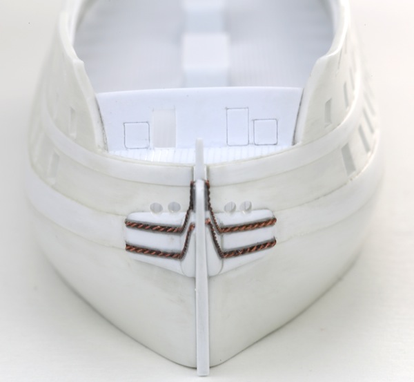
May I come back to this detail because of a technical issue I spot?
What you call the 'cheeks' of the beakhead should be in fact one solid piece: they serve as the sideways stays for the beakhead. I don't know whether 'cheeks' is the correct English word, in Dutch these were called the 'slooiknie�n', and were some of the largest pieces on board to be cut out of a of single piece of oak.
In your version there is a definite groove between the two parts, this would have rendered them technically useless (and a lot of dead weight up front, so undesirable). So I would advise to use some putty to make them whole again, probably with some additional curve to reduce the strain in the corner.
Curiously, the embellishment with the 'rope' carving runs along the whole thing, so this could have been a givaway already that these pieces should have been whole.
Maarten
"I've heard there's a wicked war a-blazing, and the taste of war I know so very well
Even now I see the foreign flag a-raising, their guns on fire as we sail into hell"
Roger Whittaker +9/13/2023
Even now I see the foreign flag a-raising, their guns on fire as we sail into hell"
Roger Whittaker +9/13/2023
-
wefalck
- Posts: 2112
- Joined: Wed Sep 28, 2011 12:04 pm
- Location: Paris
- Contact:
Re: HMS Victory and Le Redoutable at Trafalgar (1/300)
Well-spotted Maarten. These knees actually distribute a lot of the strain from the fore-rigging onto wider parts of the hull.
Eberhard
Former chairman Arbeitskreis historischer Schiffbau e.V. (German Association for Shipbuilding History)
--------------------------------------------------------------------------------------------------------------------------------------------------------------------------------------------
Former chairman Arbeitskreis historischer Schiffbau e.V. (German Association for Shipbuilding History)
--------------------------------------------------------------------------------------------------------------------------------------------------------------------------------------------
-
EJFoeth
- Posts: 2924
- Joined: Wed Jan 21, 2009 1:51 pm
Re: HMS Victory and Le Redoutable at Trafalgar (1/300)
Seams are filled with magicsculpt if you ask me, with no groove visible after painting?
Also, boiling parts also help fixing them (to a degree). Just tape them to whatever surface and throw them in the kettle...
Also, boiling parts also help fixing them (to a degree). Just tape them to whatever surface and throw them in the kettle...
-
Maarten Sch�nfeld
- Posts: 1842
- Joined: Fri Dec 12, 2008 12:44 pm
- Location: Herk-de-Stad, Belgium
Re: HMS Victory and Le Redoutable at Trafalgar (1/300)
Yeah, thanks. I just did some estimations; the beakhead has a side area of about 10 square metres. When a wave comes rolling in sideways the force will be around 50 tonnes. So without these knees the beakhead could easily break off, take the stem along, and so cause a potential lethal case for the ship, in adverse conditions. But also the side force of the fore rigging is many tonnes, just as you mentioned.wefalck wrote:Well-spotted Maarten. These knees actually distribute a lot of the strain from the fore-rigging onto wider parts of the hull.
"I've heard there's a wicked war a-blazing, and the taste of war I know so very well
Even now I see the foreign flag a-raising, their guns on fire as we sail into hell"
Roger Whittaker +9/13/2023
Even now I see the foreign flag a-raising, their guns on fire as we sail into hell"
Roger Whittaker +9/13/2023
-
Maarten Sch�nfeld
- Posts: 1842
- Joined: Fri Dec 12, 2008 12:44 pm
- Location: Herk-de-Stad, Belgium
Re: HMS Victory and Le Redoutable at Trafalgar (1/300)
I wasn't sure these knees were called 'cheeks' in English, but this image confirms the nomenclature anyway!
- images.jpg (26.78 KiB) Viewed 1512 times
"I've heard there's a wicked war a-blazing, and the taste of war I know so very well
Even now I see the foreign flag a-raising, their guns on fire as we sail into hell"
Roger Whittaker +9/13/2023
Even now I see the foreign flag a-raising, their guns on fire as we sail into hell"
Roger Whittaker +9/13/2023
-
marijn van gils
- Posts: 2697
- Joined: Tue Feb 06, 2007 10:24 am
- Location: Belgium
Re: HMS Victory and Le Redoutable at Trafalgar (1/300)
Many thanks for the nice words everyone!
I did not bend these pieces, but I cut them to this shape. Since they form the main structure for the beakhead shape they need a very specific shape, so I didn't want to risk their shape being unstable in any way. The lower rail is also cut to shape, but the middle rail (both not yet in place in these pics) was bent. The latter is very thin and not really structural. Gluing was no problem there, because there were plenty of attachment points to the head, head timbers and hull.
Cutting thin curved shapes takes some care and time. I never cut directly to the final 'line', but leave some distance and gently carve the last bit away, and finish with sanding. The concave side is the hardest, so I do that first, while leaving the piece as part of the larger plastic sheet. So basically I'm carving a concave shape out of a (stable!) edge of plastic sheet. When that is finished, I cut the piece out of the sheet, and finish the convex side.
I'll try to do a little step-by-step the next time I'm doing this, that will show this better...
I have used the boiling method before, but only for very thin items. It works very well, and I can imagine it would work with thicker items too. For simple circular curves it is quite easy (just need a glas or metal item with the correct diameter). But for more complex shapes like the main rail or head timbers some kind of former would need to be made to hold them in shape during submersion, which would be as difficult or time-consuming (or more!) as simply cutting the piece itself to shape...
I have not tried the oven yet.
Well spotted, but E-J is correct: I filled the gap with Magic Sculp, and it should look like one piece after painting.
The shape was modelled after Boudriot's plans of a typical French 74, which don't show an uninterupted curve like the cheecks of British ship of the period but show this 'kink'. The pieces are much thicker where they join than at their extremes though, but may not be very visible in my photo's?
You are right that the cheeks were crucial to hold the head together. So this has me wondering about how the French made this element structurally? Was it one piece, or two knees (under the carved parts) with the space in between and around filled in? I'll be opening Boudriot later today!
Very interesting!
Hello Christian!Christian Bruer wrote:Regarding your excellent work on the rails and head timbers, I have a question about the method you had choosen to form them. Do you cut or bent the styrene struts for the head timbers and main rails? If you bent them, would you please explain the method you have used to bent them!?
I have the problem, that small styrene struts I bent with a round tool (like a drill), tend to went back straight once I add plastic glue.
I did not bend these pieces, but I cut them to this shape. Since they form the main structure for the beakhead shape they need a very specific shape, so I didn't want to risk their shape being unstable in any way. The lower rail is also cut to shape, but the middle rail (both not yet in place in these pics) was bent. The latter is very thin and not really structural. Gluing was no problem there, because there were plenty of attachment points to the head, head timbers and hull.
Cutting thin curved shapes takes some care and time. I never cut directly to the final 'line', but leave some distance and gently carve the last bit away, and finish with sanding. The concave side is the hardest, so I do that first, while leaving the piece as part of the larger plastic sheet. So basically I'm carving a concave shape out of a (stable!) edge of plastic sheet. When that is finished, I cut the piece out of the sheet, and finish the convex side.
I'll try to do a little step-by-step the next time I'm doing this, that will show this better...
I have used the boiling method before, but only for very thin items. It works very well, and I can imagine it would work with thicker items too. For simple circular curves it is quite easy (just need a glas or metal item with the correct diameter). But for more complex shapes like the main rail or head timbers some kind of former would need to be made to hold them in shape during submersion, which would be as difficult or time-consuming (or more!) as simply cutting the piece itself to shape...
I have not tried the oven yet.
Thanks Maarten!Maarten Sch�nfeld wrote:Hi Marijn,
May I come back to this detail because of a technical issue I spot?
What you call the 'cheeks' of the beakhead should be in fact one solid piece: they serve as the sideways stays for the beakhead. I don't know whether 'cheeks' is the correct English word, in Dutch these were called the 'slooiknie�n', and were some of the largest pieces on board to be cut out of a of single piece of oak.
In your version there is a definite groove between the two parts, this would have rendered them technically useless (and a lot of dead weight up front, so undesirable). So I would advise to use some putty to make them whole again, probably with some additional curve to reduce the strain in the corner.
Curiously, the embellishment with the 'rope' carving runs along the whole thing, so this could have been a givaway already that these pieces should have been whole.
Maarten
Well spotted, but E-J is correct: I filled the gap with Magic Sculp, and it should look like one piece after painting.
The shape was modelled after Boudriot's plans of a typical French 74, which don't show an uninterupted curve like the cheecks of British ship of the period but show this 'kink'. The pieces are much thicker where they join than at their extremes though, but may not be very visible in my photo's?
You are right that the cheeks were crucial to hold the head together. So this has me wondering about how the French made this element structurally? Was it one piece, or two knees (under the carved parts) with the space in between and around filled in? I'll be opening Boudriot later today!
Very interesting!