Nice work!
I was going to make my own barrels, and I've got some Trumpeter Seagulls in the stash. Otherwise I'll probably build it mostly stock.
Calling all Brooklyn-class (CL-40) fans
Moderators: MartinJQuinn, Timmy C, Gernot, Olaf Held, Dan K, HMAS, ModelMonkey
-
Spot
- Posts: 86
- Joined: Fri Apr 28, 2017 7:01 pm
Re: Calling all USS Brooklyn/Helena class (CL) fans
The most attractive project, to me, is the one that I've just heard someone say can't be done. 
-
maxim
- Posts: 3971
- Joined: Tue Jun 14, 2005 6:23 am
- Location: Bonn
Re: Calling all USS Brooklyn/Helena class (CL) fans
I had replaced the Seagulls only, because I had built a lot of USN cruisers with them - therefore I had chosen to depict Savannah in a late fit with Seahawks.
Can you make brass barrels?
Check for the bridge - it could be, that the combination of Seagulls and the bridge depicted in the kit is not possible. As far as I understand it, she got an armoured bridge after the conversion, which was later removed. On Navsource there is a 1945 photo with a open bridge (as in the kit), but with Seahawks. Seahawks are also available from Trumpeter.

-
Spot
- Posts: 86
- Joined: Fri Apr 28, 2017 7:01 pm
Re: Calling all USS Brooklyn/Helena class (CL) fans
Actually I make scratch-built models mostly of wood, and if the plastic/resin kit I'm working with might benefit, I make my own barrels as an upgrade.maxim wrote: Can you make brass barrels?
I have some seahawks too, but I like those seagulls.
If I were doing a scratch-build of Savannah I would represent her as she was during the Sicily campaign. The amount of modification I'm going to do to the kit is limited. It's a project I'm doing while recuperating from some medical issues, so it's going to be mostly from the box. I've also found that the rivet-counter I was becoming for a while was having less fun building models than I used to, so I'm trying to train myself away from the obsession. :p
The most attractive project, to me, is the one that I've just heard someone say can't be done.
-
Woozer
- Posts: 2
- Joined: Fri Aug 14, 2020 6:24 pm
Calling All USS Helena (Cl-50) Fans
Hello everyone,
I'm trying to figure out CL-50 Helena's signal flags, particularly the ones that were flown during her final remodel/engagement at Kula Gulf.
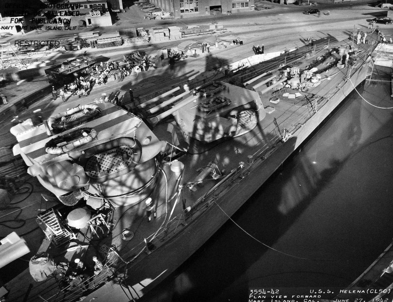
I was also curious as to when Helena lost her green "Cruiser Division 9" ID stripes on her #2 and #4 turrets. It seems that she still had the stripes in June of 1942.
I was unable to find too much on the subjects, would anybody be able to point me in the right direction?
I'm trying to figure out CL-50 Helena's signal flags, particularly the ones that were flown during her final remodel/engagement at Kula Gulf.
I was also curious as to when Helena lost her green "Cruiser Division 9" ID stripes on her #2 and #4 turrets. It seems that she still had the stripes in June of 1942.
I was unable to find too much on the subjects, would anybody be able to point me in the right direction?
-
taskforce48

- Posts: 1612
- Joined: Mon May 21, 2007 5:49 pm
- Location: The beautiful PNW
Re: Calling all USS Brooklyn/Helena class (CL) fans
Sorry not sure I can help with that, being a night engagement I am not sure if any signal flags were being employed.Woozer wrote:I'm trying to figure out CL-50 Helena's signal flags, particularly the ones that were flown during her final remodel/engagement at Kula Gulf
Can't provide a date for you, but it does appear that the ones visible were the same we see on her, including the rafts on 12/7/41.Woozer wrote:I was also curious as to when Helena lost her green "Cruiser Division 9" ID stripes on her #2 and #4 turrets. It seems that she still had the stripes in June of 1942.
USN Shipyard practice was to usually save all vertical painting for last before departing the yard. Possible these were just still in place from prior issued orders. We do see the USS Vincennes still had her's around this same time, so it also may have been at some commander's discretion.
This image in the Australian War Memorial collection claims to be March 5th of 43', not super crisp but it doesn't appear to my eye's to show the markings still in use.

Unfortunately images of her wreck aren't clear enough and what can be seen is covered in marine growth and inconclusive to see if they were still there at time of her loss.
Hope this is of some help.
Matt
In the yards right now:
USS Utah AG-16
On Hold
1/350 USS Portland CA-33 1942
1/350 Trumpeter Texas with a twist
USS Utah AG-16
On Hold
1/350 USS Portland CA-33 1942
1/350 Trumpeter Texas with a twist
-
Don Andrews

- Posts: 26
- Joined: Mon Jan 09, 2006 1:00 am
- Location: San Jose, CA
Re: Calling all USS Brooklyn/Helena class (CL) fans
Considering Helena was (as seen) in drydock for repairs, post 12/7/41, and then went immediately to MINY, it is highly unlikely she kept the willow green stripes in her turret tops much past these repairs. In the above picture of her in 43, wearing overall 5-N, she is not wearing turret stripes; all horizontal surfaces are in 20-B.
-
Rick E Davis
- Posts: 3871
- Joined: Thu May 29, 2008 8:02 pm
Re: Calling all USS Brooklyn/Helena class (CL) fans
It didn't take a yard period for a ship to do some painting/repainting. Every USN warship had a normal practice of touching up paint during down times to reduce corrosion. If the ship's CO (or higher) directed that the pre-war stripes had to go, they went. It wouldn't have taken very long to do so.
-
Ian Roberts
- Posts: 314
- Joined: Sun Jan 08, 2012 4:59 pm
- Location: Austin
- Contact:
Re: Calling all USS Brooklyn/Helena class (CL) fans
Hi all -
For the life of me, I can't find the earlier discussion that covered the prop guard locations on the ST LOUIS and HELENA vs. the BROOKLYNs and CLEVELANDs. I've searched both CASF threads to no avail.
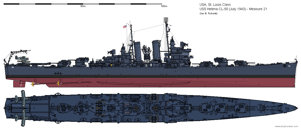
I'm wondering about this because the Alan Chesley drawings of HELENA show the prop guard in the correct location (according to photographs) -- almost abeam the after 6" turret. However, these same drawings show the outboard propeller aft of this position which makes no sense to me. Surely the prop guard would be centered exactly over the outboard propeller?
Here is the drawing in question:
Here's a crop of NH 95816, showing CL-50 off Boston on 6/15/1940:
As you can see the Chesley plans show the prop guard in roughly the correct location and line up nicely with the pre-war photo.
My suspicion is that the underwater hull drawing from Mr. Chesley shows the outboard prop in an incorrect location. For what it's worth, multiple other illustrations of HELENA perpetuate this error (I suspect they were traced from the original Chesley plans of 1979 without consideration for these sorts of details). Is it possible the Chesley plans used the underwater hull of the BROOKLYN class cruisers incorrectly? My assumption then is that the rearranged machinery in ST LOUIS and HELENA resulted in slightly different underwater configurations, but I haven't found any plans of ST LOUIS or HELENA that prove this one way or the other. I've ordered the 1935 "general arrangement" drawings of ST LOUIS available from Floating Drydock hoping they will show the configuration and answer this question...
Thanks all!
For the life of me, I can't find the earlier discussion that covered the prop guard locations on the ST LOUIS and HELENA vs. the BROOKLYNs and CLEVELANDs. I've searched both CASF threads to no avail.
I'm wondering about this because the Alan Chesley drawings of HELENA show the prop guard in the correct location (according to photographs) -- almost abeam the after 6" turret. However, these same drawings show the outboard propeller aft of this position which makes no sense to me. Surely the prop guard would be centered exactly over the outboard propeller?
Here is the drawing in question:
My suspicion is that the underwater hull drawing from Mr. Chesley shows the outboard prop in an incorrect location. For what it's worth, multiple other illustrations of HELENA perpetuate this error (I suspect they were traced from the original Chesley plans of 1979 without consideration for these sorts of details). Is it possible the Chesley plans used the underwater hull of the BROOKLYN class cruisers incorrectly? My assumption then is that the rearranged machinery in ST LOUIS and HELENA resulted in slightly different underwater configurations, but I haven't found any plans of ST LOUIS or HELENA that prove this one way or the other. I've ordered the 1935 "general arrangement" drawings of ST LOUIS available from Floating Drydock hoping they will show the configuration and answer this question...
Thanks all!
-
DrPR

- Posts: 1689
- Joined: Sun Mar 07, 2010 12:01 am
- Location: Corvallis, Oregon, USA
- Contact:
Re: Calling all USS Brooklyn/Helena class (CL) fans
Ian,
It will be interesting to see what you learn about the propeller guard position.
I not very familiar with the Brooklyn/Helena class prop arrangement, but with the Clevelands which were similar the outboard props extended outboard beyond the hull waterline and were susceptible to hitting underwater pier framing, sea walls, etc. Hence the prop guard was positioned directly over the outboard propeller to prevent it from coming in contact with piers and sea walls.
If you want to get a Captain really twitchy just get the stern of a ship close to something. The Navy really frowns upon banging up props! It's the career path to a desk job.
One time in Sasebo, Japan, our Captain took the conn from the harbor pilot when the guy was swinging the stern toward a rock wall. That is really unusual - the pilots normally conn ships in and out of harbor.
Phil
A collision at sea will ruin your entire day. Aristotle
-
Captain Morgan

- Posts: 255
- Joined: Wed Jan 12, 2005 6:14 am
- Location: SE Michigan
Re: Calling all USS Brooklyn/Helena class (CL) fans
If you compare the Savannah battle damage drawing to the USS Houston CL-81 battle damage plate you will see the forward (outer) props are just forward of frame 125 on the Cleveland class ships, while aft of frame 125 on the Brooklyn class. The Helena and St Louis have the same engineering plants as the Cleveland class not the Brooklyn class. I mean this as both in layout and in steam pressure. By moving the props forward in theses ships you keep from making extremely long outboard shafts with the extra torsional stress on them. The St Louis subclass was the first light cruisers with unit propulsion which had alternating boiler rooms and engine rooms. The extra separation was supposed to help with battle damage mitigation. But if you see what happened to the Houston, the torpedo exploded below the starboard fwd engine room destroying the turbines and reduction gear and flooding both sets of boiler rooms putting her dead in the water.
Last edited by Captain Morgan on Fri Jan 08, 2021 6:53 pm, edited 1 time in total.
My CO prior to flying to the boomer: Our goals on this patrol is to shoot missiles and torpedoes.
Me: Capt don’t we really want to be like Monty Python and not be seen?
LT you seem to be missing the big picture
Oh
Me: Capt don’t we really want to be like Monty Python and not be seen?
LT you seem to be missing the big picture
Oh
-
tjstoneman
- Posts: 443
- Joined: Mon Mar 02, 2009 11:33 am
Re: Calling all USS Brooklyn/Helena class (CL) fans
According to many references, the engineering plant in Helena and St Louis differed significantly from that in Brooklyn and her sister ships. The two later ships adopted a unit system, which put the forward enginerooms ahead of the after fire-rooms, and thus the outer propellor shafts were considerably longer than those in Brooklyn. Further, newer technology allowed more efficient steam conditions (temperature/pressure 700?/565psi) compared to Brooklyn's (648?/400psi), resulting in ssmaller machinery.
-
Keith T. Bender
- Posts: 499
- Joined: Thu Mar 20, 2008 10:22 pm
Re: Calling all USS Brooklyn/Helena class (CL) fans
Here's the deal. Ships that have prop guards will always have the guard right above the propellers. Only change in this could be if one was destroyed and it was quickly repaired and not placed in the correct position. However that shouldn't be the case because in most cases there would be tell-tail signs of where the former guard was on the hull and a new one would be put back in it's place, hopefully. So with this you can count on the plans are draw incorrectly. I've found using Chesley and Wiswesser plans can get you in trouble. I do not say that as a dig toward these two men but a fact is a fact.
I've know Ed Wiswesser for 40 years personally until his death at 100 years.
I've know Ed Wiswesser for 40 years personally until his death at 100 years.
-
Ian Roberts
- Posts: 314
- Joined: Sun Jan 08, 2012 4:59 pm
- Location: Austin
- Contact:
Re: Calling all USS Brooklyn/Helena class (CL) fans
Thanks for confirming my suspicions I guess we will know for sure once I receive the plans of ST LOUIS.
I have found the Chesley plans of HELENA to be fairly accurate (matching photos), with the exception of the propeller guard and the dimensions of the open bridge. Dick J points out earlier in this thread how all existing plans of the ship don't get this area correct -- Chesley and Profile Morskie show the open bridge to be far too wide and this does not match the photos at all.
Unfortunately, these two resources seem to be the only commercially available plans for CL-50 as lost. I wonder what treasures lay buried at NARA
-
Ian Roberts
- Posts: 314
- Joined: Sun Jan 08, 2012 4:59 pm
- Location: Austin
- Contact:
Re: Calling all USS Brooklyn/Helena class (CL) fans
While we're on this subject -- does anyone know the color scheme and markings for the SOC Seagull cruiser scouts aboard HELENA in July 1943? William T. Larkins' book "Battleship and Cruiser Aircraft of the United States Navy 1910-1949" states that HELENA had aboard 2x SOC-3 and 2x SON-1 of VCS-9 in Nov 1942 -- the next available date for aircraft assignment in this book is August 1943, after which HELENA had been sunk.
I found some interesting video clips available on Critical Past which show cruiser scout operations around this timeframe aboard HONOLULU (HELENA is even visible in the background of some of these shots). Both clips are dated 13 May 1943. HONOLULU is mentioned in the Nov 1942 aircraft assignment as carrying 2x SOC-1 and 2x SOC-2, also of VCS-9. I am not an expert in identifying aircraft color schemes, but the markings are the obvious large circular blue/white roundel (no red elements) with no white bars, but I can't tell if the aircraft paint scheme is the earlier blue-gray over light gray, or the 1943 tricolor.
Here are the clips in question:
https://www.criticalpast.com/video/6567 ... lulu-CL-48
https://www.criticalpast.com/video/6567 ... gull-plane
With nothing else to go off, my assumption would be to copy the scheme and markings on these aircraft aboard HONOLULU for my drawing of HELENA -- unless of course other evidence is brought forward!
Any help is appreciated!
-
Mike C

- Posts: 578
- Joined: Wed Jan 12, 2005 1:32 am
- Location: Peach State
Re: Calling all USS Brooklyn/Helena class (CL) fans
I'd say the paint scheme in both clips is glue-gray over gray, which is the usual paint for the stars without bars.
-
Ian Roberts
- Posts: 314
- Joined: Sun Jan 08, 2012 4:59 pm
- Location: Austin
- Contact:
Re: Calling all USS Brooklyn/Helena class (CL) fans
The mystery continues. I received the "general arrangement" plans of CL-49/CL-50 from Floating Drydock -- for one, they show an early draft design of the ships that looks more akin to the BROOKLYN than the as-built design. Interestingly, the shaft arrangement and propeller guard seems to be the same as later plans -- with the propeller guard not situated above the outboard propeller.Ian Roberts wrote:Thanks for confirming my suspicions
I have found the Chesley plans of HELENA to be fairly accurate (matching photos), with the exception of the propeller guard and the dimensions of the open bridge. Dick J points out earlier in this thread how all existing plans of the ship don't get this area correct -- Chesley and Profile Morskie show the open bridge to be far too wide and this does not match the photos at all.
Unfortunately, these two resources seem to be the only commercially available plans for CL-50 as lost. I wonder what treasures lay buried at NARA
-
DrPR
- Posts: 1689
- Joined: Sun Mar 07, 2010 12:01 am
- Location: Corvallis, Oregon, USA
- Contact:
Re: Calling all USS Brooklyn/Helena class (CL) fans
After looking a a bunch of USS Brooklyn CL-40 photos on Navsource I think the propeller guard is positioned correctly with respect to the after turret, about even with the ends of the gun barrels. So the question is whether or not the location of the outboard propeller is correct in the drawing.
There is only one photo showing the ship in the ways before launching from an oblique stern view that shows the underwater configuration. The propeller has not been installed, but it looks like it is closer to the position of the propeller guard than the drawing shows it.
In the USS Savannah CL-42 section I found this war damage report (after being hit by the German Fritz-X glide bomb). Notice that the outboard propeller is shown about even with the ends of the gun barrels on the after turret at about Frame 126 - about where the propeller guard is positioned in your drawing at the aft end of the armor belt.
Broadside photos of the USS Honolulu CL-48, USS Boise CL-47 and USS Phoenix CL-46 appear to show the propeller guard in the position shown in your drawing!
These were all Brooklyn class ships.
Pictures of the USS St. Louis CL-49 appear to show the propeller guard farther forward outboard of the face of aft turret, at about Frame 122 which would place the outboard propeller in about the position shown in your drawing, with the propeller guard in the wrong position.
Drydock photos of the USS HelenaCL-50 show similar positioning of the propeller guard relative to the outboard propeller. The position relative to the aft turret is not shown. Unfortunately the battle damage report for the Helena doesn't show the propellers or propeller guard.
St. Louis and Helena were both "modified Brooklyn class" or St. Louis class.
Drawings in Norman Friedman's "USS Cruisers" page 209 show the Helena outboard propeller position several frames aft of the ends of the gun barrels on the after turret. Pictures of the Brooklyn (page 199) show the outboard propellers farther forward at about the ends of the gun barrels. Both show the propeller quite a but more aft than in your General Arrangement drawing.
All of this is inconclusive, but it looks as if the St. Louis and Helena may have had the outboard propeller farther aft than in the other Brooklyn class ships. Given the drastic rearrangement of the engineering spaces on the St. Louis class it wouldn't be surprising to see a change in position of the propellers.
You have to take the General Arrangement plans with a grain of salt. They were often conceptual drawings made before the ships were actually built, and before modifications had been made to the design. In the case of the drawing you have it might have been drawn up from an early Brooklyn class hull drawing with modification for the St; Louis class.
If you are going to look at the blueprints in the National Archives try to find the actual drawings for the propeller guard as well as the propeller and propeller shaft drawings to see where they were installed (frame numbers). Again, sometimes the general arrangement drawings in the blueprints do not actually show where things eventually ended up being placed. Also, different shipyards sometimes changed things to suit their practices with approval from BuShips (often afterward).
Phil
- Attachments
-
A collision at sea will ruin your entire day. Aristotle
-
Ian Roberts
- Posts: 314
- Joined: Sun Jan 08, 2012 4:59 pm
- Location: Austin
- Contact:
Re: Calling all USS Brooklyn/Helena class (CL) fans
Thanks for your detailed reply Phil! I suspect you're right that the drawing I received just has the prop guard positioned incorrectly (it was likely based off earlier BROOKLYN class drawings).
For my own rendition of HELENA in July 1943, I placed the prop guard in the position verifiable by photos and moved the outboard prop and shaft to match. If I'm ever able to make it to NARA and examine the microfilm for these ships I plan to come back and ensure the shafts are drawn correctly - this is my "best guess".
For my own rendition of HELENA in July 1943, I placed the prop guard in the position verifiable by photos and moved the outboard prop and shaft to match. If I'm ever able to make it to NARA and examine the microfilm for these ships I plan to come back and ensure the shafts are drawn correctly - this is my "best guess".
-
DrPR
- Posts: 1689
- Joined: Sun Mar 07, 2010 12:01 am
- Location: Corvallis, Oregon, USA
- Contact:
Re: Calling all USS Brooklyn/Helena class (CL) fans
Ian,
I suspect the prop positions in your drawing are for the early Brooklyns, and St. Louis and Helena had them a bit farther aft - but that is a poorly educated guess!
You could just order the microfilm on DVD from the National Archives and save the cost of a trip (depending upon where you live). I am in Oregon so a trip is just not practical. It was cheaper for me to order all of the Cleveland class microfilms.
Unfortunately, I suspect there will not be a single index reel for the Brooklyn/St. Louis class. The USS Cleveland CL-55 microfilm has an index at the beginning of each reel listing only the blueprints on that reel, so I had to order all 19 reels. Most were door and furniture lists, lists of label plates over doors, wiring, plumbing and ventilation diagrams, etc. of no use for modelling. However, by the time of the modified Cleveland in the early 1940s each collection had a separate index reel that listed all blueprints on all physical reels. This was very useful for determining if a desired blueprint was actually in the collection. Many of the Cleveland blueprints were lost and are not in the microfilm collection.
****
The drawings are in the same order on the microfilm as the Ship Material Group Codes (attached). If you know the number of reels in the drawing collection (the Archivists can tell you that) you can guess which reel might contain a drawing you need. However some material groups are larger than others, and some may fall across multiple reels.
Fortunately, information about the position of the propellers will likely be on reel 1 in the S1 Design of vessel and S7 Docking (drydock) sections. S1-3 has general plans (but not necessarily accurate) and S5 Molds has hull line plans. Section S11 Hull structural and S12 hull fittings will contain the actual construction blueprints showing individual hull plates, etc. All of these sections should be on reel 1. But if there is a separate index reel (the Archivists can tell you this) the plans will start on reel 2.
S43 Shafting and bearings (S43-2 Bearings) has drawings of the propeller shaft struts and S44 Propellers has the prop drawings. In the Cleveland plans the prop struts were on reel 2 and the propellers on reel 10 along with some shaft details and fairings.
****
A word of caution: There are reels and there are reels! For some reason the entire collection of drawings for a ship is called a "reel." So the Cleveland drawings are microfilm Reel # 5537. But in this collection there are 19 physical reels of microfilm containing 4630 individual blueprints. But each individual blueprint may have been photographed in as many as six overlapping "frames" or photographs.
I got all of my copies on actual microfilm (before the Archives started offering scanned images on DVDs). I do not know how they organize the images or frames on the DVDs. Each physical reel may be scanned to a separate DVD, or multiple physical reels may be placed on one DVD. You need to ask an Archivist about this.
Hope this helps.
Phil
A collision at sea will ruin your entire day. Aristotle
-
Rick E Davis
- Posts: 3871
- Joined: Thu May 29, 2008 8:02 pm
Re: Calling all USS Brooklyn/Helena class (CL) fans
Ian,
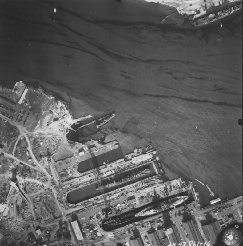
I'm pretty sure that wasn't the configuration for USS ST LOUIS in July 1943. More like July 1944 (when she was painted in dazzle) with additional changes like searchlight tower removed.
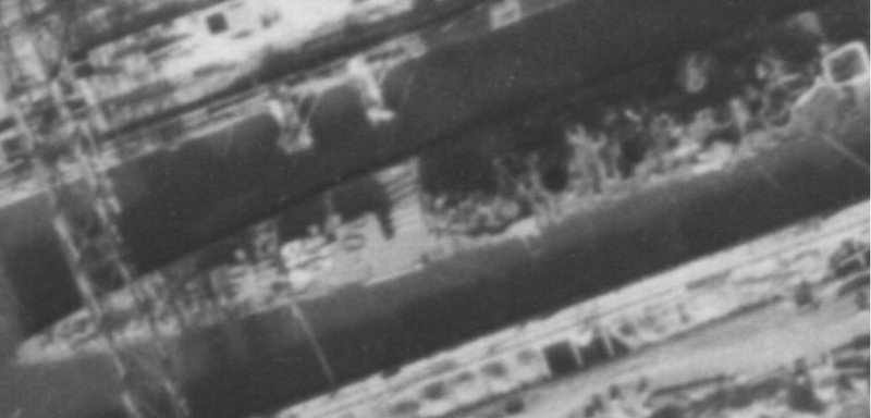
First image is dated 5 July 1943. Second image was taken after she was torpedoed. I see at least two twin 40-mm mounts per side and no quad 40-mm mounts yet?
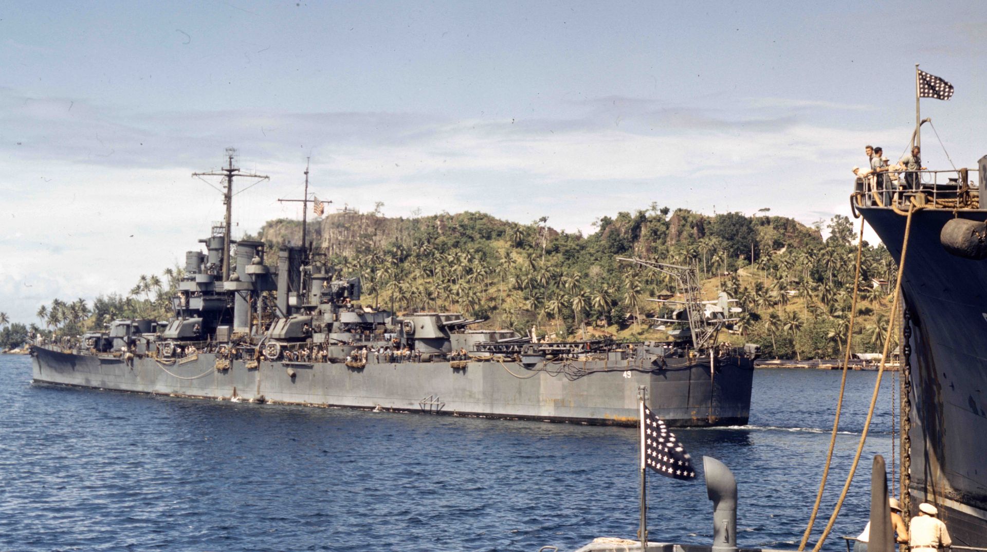
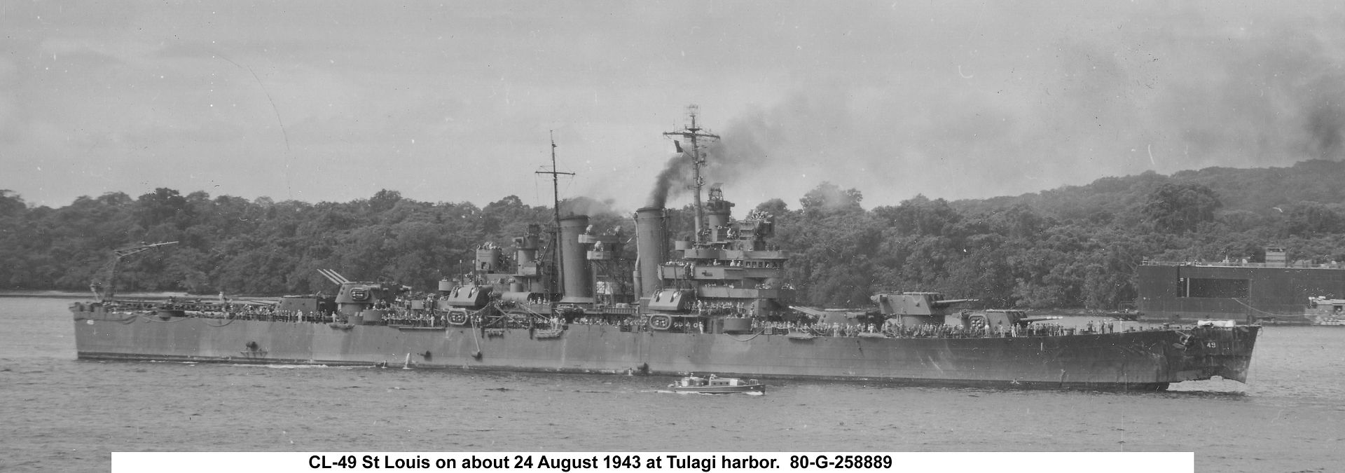
I'm pretty sure that wasn't the configuration for USS ST LOUIS in July 1943. More like July 1944 (when she was painted in dazzle) with additional changes like searchlight tower removed.
First image is dated 5 July 1943. Second image was taken after she was torpedoed. I see at least two twin 40-mm mounts per side and no quad 40-mm mounts yet?