Page 7 of 11
Re: USS Oklahoma City CLG-5
Posted: Fri Apr 08, 2016 3:57 am
by Aur
Hello Phil,
A very, very complex 3D model!

Lucky for those who make USS Oklahoma City models - they really get the best reference for their builds!
Hope to see her finished soon

Best regards,
Aur
Re: USS Oklahoma City CLG-5
Posted: Sun Apr 10, 2016 1:14 am
by DrPR
Aur,
Thanks. Right now I am swamped with other work and have had to stop work on the model for a while. But I should be back at it in a week or two.
Someday I want to use the 3D model to produce a detailed set of plans for the ship. But right now everything is more or less in an incomplete state. I am still finding corrections for all parts of the ship, but most are pretty minor.
Phil
Re: USS Oklahoma City CLG-5
Posted: Sun Apr 10, 2016 7:37 am
by jpeeler
This is an amazing and fascinating project, Phil. I'm not only learning a lot in the process, but I'm awed by how thorough you are in chasing down so many little details, and getting things as correct as you can. My hat's off to you for the way you're bringing CLG-5 back to life. I look forward to what's ahead.
Jodie Peeler
Re: USS Oklahoma City CLG-5
Posted: Sun Apr 10, 2016 11:18 pm
by DrPR
Jodie,
Thanks. Someday I hope to be able to use this CAD model as the basis for a walk through video. Right now that is a bit out of my league - not enough time or processor horsepower. But someday people may be able to take a virtual tour of the ship's decks, just like the open ship days we had for visitors when I was aboard.
Phil
Re: USS Oklahoma City CLG-5
Posted: Tue Apr 26, 2016 3:03 pm
by DrPR
I'm still plodding along adding details to the forward deck house. Real life events keep interfering with the modeling.
I thought I would post a word of caution for those who might consider modeling one of the CLGs. Twice now I have gotten confused as to the elevations of the decks in the forward superstructure. I have most of the blueprints for the CLG TALOS conversion - which are actually for the USS Little Rock CLG-4, the OK City's sister ship. For dimensional details I refer to these blueprints.
The Outboard Profile drawing (Reel 1 Frame 9) gives the elevations of the decks above the Base Line (the Base Line is the inside top of the keel plating, or 1 11/16 inch above the bottom of the keel for the Cleveland class). Today I was trying to reconcile some elevations calculated from photographs (photoguesstimation) and my CAD model, and it appeared I had placed the O2 and O4 decks at the wrong elevations! That would be bad news!
But then I checked the Inboard Profile drawing (Reel 1 Frame 12) and found that it did not agree about the deck elevations with the Outboard Profile drawing. My CAD model used the Inboard Profile elevations, which are 1" higher for the O2 level and 6" higher for the O4 level! At this point I remembered that I already went through this back in November 2015 when I started work on the forward superstructure - one of the pitfalls of not being able to work continuously on the model.
Just to be sure I looked at the actual construction blueprints for each part of the forward deck house and I found that the measured dimensions given in these working drawings agree very closely, if not exactly, with the Inboard Profile. Oddly, the Outboard Profile drawing was dated later than the Inboard Profile and the deck house working drawings. Maybe the draftsman just made a mistake writing in the elevations?
****
This illustrates the problem with working from the Outboard Profile drawings found in blueprint sets and in the Book of General Plans. The original Outboard Profile drawings are just sketches of what the designers think the ship will look like at the beginning of the design process. The final product (the commissioned ship) may be significantly different.
I know there are some drawings of the USS Long Beach CGN-9 that show the elevation of the top of the forward superstructure quite a bit off, so it is always good to double check the numbers when you can.
Phil
Re: USS Oklahoma City CLG-5
Posted: Tue Jun 07, 2016 12:03 am
by DrPR
Making slow progress. May was incredibly busy - don't think I had time to do any work on the model. Less hectic now.
I have (almost) finished detailing the lower starboard side and detailed the lower port side. 470,000 entities in the drawing, with 3.7 million points. 325 megabytes - It is getting cumbersome to work with.
Still need to work on the O2 and O3 levels, and details at the aft end of the deck house. Lots of mooring line reels, more searchlights, binoculars and refueling stations. Then I will work on the details of the bridge wings and pilot house. Next will be adding the Mk37 director and a dozen or so life rafts. Finally the forward radar tower will be added, and the wire antennas, ship's flags and pennants will be rigged.
Phil
Re: USS Oklahoma City CLG-5
Posted: Thu Jun 23, 2016 10:15 pm
by DrPR
Here is another detail for the forward superstructure. This is the 40mm saluting gun. The OK City was a flagship and we visited a lot of ports and hosted many dignitaries - all calling for salutes.
The saluting guns were an oddity on the CLGs - they were positioned at different places on most of the ships. On the OK City and the USS Little Rock they were on small outboard platforms at the O1 level, but some ships had them on the O4 level.
I have never found plans for these guns, but photos from WWII ships and modern era ships show they were essentially the same over the years. I concocted this design from many ship photos and even a publicity photo for a movie. It is pretty much a "Heinz 57" variety.
If anyone has plans for the real thing - or good close-up photos - I would appreciate having them.
Phil
Re: USS Oklahoma City CLG-5
Posted: Mon Aug 08, 2016 3:54 pm
by DrPR
More progress on the forward superstructure. I think I have finished all of the nit-picking details like water washdown piping, lights, switches, wiring, etc. But there still may be a fire plug and hose on the port O3 level - I just don't have clear photos of that area.
Next I need to detail the open bridge wings - Captain's chair, wood gratings, pelorus, etc. Someday I will detail the enclosed navigation bridge and pilot house.
There are two more searchlights to do, and I need to add the big binoculars and the Mk 37 director. The last details to add will be about a dozen life rafts. That will increase the file size quite a bit and slow things down even more than they are now.
After that I will add the huge forward radar tower to finish it off - that will bring the file up to about 280 Mbytes. Then working with it will be very slow!
I ran into a snag a couple of weeks ago. When I started the forward superstructure several years back I mistakenly read a blurry dimension from a blueprint. Instead of setting a point 12 inches forward of a frame I put it 18 inches forward. After that I occasionally found things that just didn't fit right. Well, I found the error just as I thought I was about finished with the navigation bridge, and had to redraw most of the navigation bridge and flag bridge! But now things fit together nicely.
That was the whole point in creating the CAD model in the first place - to be sure the parts fit together before I start cutting material and spending time on the real 1:96 model.
Phil
Re: USS Oklahoma City CLG-5
Posted: Sun Aug 21, 2016 2:59 pm
by DrPR
More detail work on the forward superstructure. Searchlights, binoculars and the deck gratings, pelorus (gyro repeater), rudder angle indicator and Captain's chair on the open bridge wings.
Next will be the Mk 37 director. I last worked on it eight years ago so I imagine there will be some tweaking to do before I put it in the superstructure file. Then I'll add the life rafts and that should bring it up to readiness for adding the forward radar tower. The file should be about 250 Mbytes before adding the 59 Mbyte tower. 300 Mbytes will be pretty slow to work with.
Phil
Re: USS Oklahoma City CLG-5
Posted: Sun Aug 21, 2016 3:07 pm
by Ian Roberts
A truly incredible piece of work. I've greatly enjoyed following your progress; one day I hope to be as proficient with a 3D modelling program as you!
Re: USS Oklahoma City CLG-5
Posted: Sun Aug 21, 2016 11:42 pm
by DrPR
Well you might want to think it through a bit, because my intuition tells me you have to be a little crazy to try to put in all the nuts and bolts.
Phil
Re: USS Oklahoma City CLG-5
Posted: Tue Aug 23, 2016 2:07 pm
by DrPR
The Mk 37 director needed a little rework from the file I created eight years ago. Minor detail changes, but I did manage to reduce the file size by 20%.
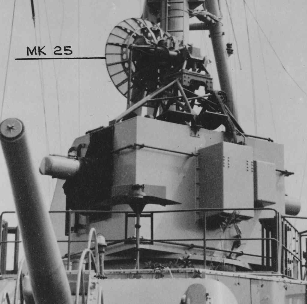
This is the Mk 37 with the Mk 25 radar. The ship originally (early 1960s) had a screened parabolic dish antenna for the Mk 25. But by 1967 this had been replaced by the solid parabolic dish shown here.
The original Mk 37s did not have radar and used optical sights. During WWII the Mk 12 radars were installed and then replaced with the newer Mk 22 radar. Mk 25s were introduced in 1945 with the screened dish antenna. The optical sights were still used to make fine adjustments to bearing and elevation.
Mk 37s were found on auxiliaries, destroyers, cruisers, battleships and aircraft carriers. They all looked alike, more or less. But the shields were of different thickness armor plate to reduce topside weight on smaller ships.
1630 and 1850 ton destroyers - 1/8"
Auxiliaries - 5/8"
Larger destroyers - 1/2" and 3/4"
Cruisers - 1"
Carriers - 1"
Earlier battleships - 1"
Later battleships - 1 1/2"
The original directors had three windows in front. They did not have the Director Officer's cockpit with the open seat and the black canvas folding cover shown here - it must have been hot inside! I stood Director Officer's watch part of the time I was on the OK City, and that open cockpit was the highest manned station on the ship. The view was great and it was a good place to get a tan! Off Vietnam, where it was very warm, when we weren't shooting at something the director crew opened all the hatches and sat on top to catch rays. The best seat in the house!
The OK City used the Mk 37 to direct both the 6"/47 main battery and the 5"/38 secondary battery. All CLGs retained the original Cleveland Mk 34 director for the 6" battery, but this was removed from the Oklahoma City (and only the Okieboat) in the mid 60s to reduce topside weight. This is an easy way to distinguish the Oklahoma City from the other CLGs.
Phil
Note: Edited to correct mistakes pointed out by Rick 23 Aug.
Re: USS Oklahoma City CLG-5
Posted: Tue Aug 23, 2016 2:14 pm
by maxim
Really impressive! And good stories and explanations!
Re: USS Oklahoma City CLG-5
Posted: Tue Aug 23, 2016 5:09 pm
by DrPR
Here is another story about the Mk 25 radar.
The Mk 25 on the OK City stopped working and the Navy flew out a technician from the States to work on it. It turns out that one of the circuit boards had old TO-5 three wire leaded transistors on it. The wires were copper, but MIL-SPEC parts had to be gold plated to resist corrosion - a few thousandths of an inch of gold over the copper. One of the transistors had a microscopic hole in the gold plate on one lead, and years of salt corrosion had removed all of the copper, leaving just a very thin and fragile gold tube. Eventually vibration - or just the weight of the transistor - broke the gold tube, breaking the electrical connection and the transistor failed. The technician said this happened all the time in older installations.
We also had to replace a transmitting tube in the radar - there were two of them as I recall, and the ship was supposed to carry two spares. So we had to order a replacement. But no one made the tubes any more, and spares were in very short supply. So the Mk 25 technician carried spares with him wherever he went because many ships didn't have any.
Eventually the Navy would run out of spare tubes and would have to order more. But there were no existing assembly lines and the manufacturers would charge the navy for a batch of new tubes AND a new assembly plant to make them. After the order was filled the assembly plant would be dismantled and the space used for something else. So every time the Navy needed to order a new batch of tubes it would cost millions of dollars. I think each tube sold for something like $35,000 in 1970s dollars (I bought a new 1972 Chevy Camaro for $3,216.00). You could buy two houses for $35,000.
Phil
Note: edited to correct errors pointed out by Rick Davis. Thanks Rick!
Re: USS Oklahoma City CLG-5
Posted: Tue Aug 23, 2016 6:26 pm
by Rick E Davis
Phil,
Your history/nomenclature for Mk 37 director radars is a little off. My tutorial is focused on USN destroyers, but the Fire Control Radars used on Mk 37 directors on any USN ship were the same (different Mods maybe).
The Mk 37 director true enough didn't have radar when first introduced on the SIMS class destroyers. But, the first radars installed on destroyer Mk 37 directors were in September 1941 with the first being the
FD (Mk 4) radar. The Mk 4 radars were improved with various mods until replaced with the Mk 12 radar in 1944 on new construction.
The
Mk 12 radar was intended to be paired with the
Mk 22 "orange-peel" radar to improve low altitude performance and better height angle determination on the "Square-Backed" Mk 37 directors. The Mk 22 radar development lagged behind the Mk 12 by a few months, so some destroyers (unsure about cruisers, etc) went into service without the Mk 22. Most however had the Mk 22 added during Post-Shakedown. The
Mk 12/22 radar pairing was common on most USN ships with Mk 37 directors by the end of WWII.
The late war replacement for the Mk 12/22 radars was the
Mk 25 radar, not the Mk 28. The
Mk 28 radar was a smaller radar (with a smaller dish antenna) intended to be installed on the destroyers with the older "Taper-back" Mk 37 director that couldn't accommodate the Mk 12/22. The Mk 28 was installed on SIMS-BENSON-GLEAVES class destroyers and GLEAVES class DMS units and some older destroyers with earlier directors.
The
Mk 25 radar didn't finish development until post-WWII and started to see fleet-wide installation/replacement for Mk 4 and Mk 12/22 radars in about 1949.
I don't have an Armament Summary Listing for any of the CLG's, but here is one for CAG-2 in 1960. As you can see she had a single Mk 25 radar that were installed on the Mk 37 director and six Mk 35 radars installed on the six Mk 56 GFCS.
Re: USS Oklahoma City CLG-5
Posted: Tue Aug 23, 2016 11:11 pm
by DrPR
Rick,
Thanks. I was in a hurry and didn't research the early fire control radars in depth. I was quoting Ordnance Pamphlet 2 for the Mk 37 that I got from Floating Drydock. I thought I remembered it being a Mk 25 on the OK City's Mk37.
And I am not sure if there was a Mk or Mod change when the antenna dish was changed in the 1960s from the screen to the solid reflector.
Phil
Re: USS Oklahoma City CLG-5
Posted: Wed Aug 24, 2016 5:57 pm
by DrPR
Finally, after nine months the forward superstructure is (almost) done. I say almost because there are a few details I am not certain about and I need to decide what signal flags will be flying and add two wire antennas.
315 Mbytes, 6,460,977 points and 847,080 entities in the drawing!
The majority of the work is done on the model - I'd estimate 95%. There are some details to add to the main deck on the hull - lifelines and such, and a bunch of nets around the flight deck. Then I can put it all together.
I want to create a set of 2D drawings from the model and that will take quite a while to finish.
Phil
Re: USS Oklahoma City CLG-5
Posted: Thu Sep 01, 2016 10:34 pm
by DrPR
I was looking back over pictures of the Mk 37 director and noticed a detail that I had missed.
On the optical range finder arms there is a bit of plumbing. In some pictures it looks like solid pipes and in others I can see what appears to be sections of pipe joined by pieces of rubber hose with hose clamps. In the middle is what appears to be a solenoid valve.
My guess is that is is compressed air piping with an electrical valve. Perhaps it was used to blow water/dust off the lens, or maybe it was used to blow off the caps that normally were fitted over the lens tube when the director wasn't being used.
Does anyone know for sure what this was for?
The Mk 37 instruction manual says the optical rangefinder operator should remove the lens caps, but it doesn't say how. He could climb out on the side ladder and pull them off by hand, but the compressed air "ejector" could be operated from inside much quicker.
Note: The lens caps were attached to the structure with short chains (not shown) so they wouldn't be lost when they were removed.
****
This piping was not installed on the directors in 1941, but appears to have been common in late 1942.
Phil
Re: USS Oklahoma City CLG-5
Posted: Fri Sep 02, 2016 6:48 pm
by Ian Roberts
I think I remember reading somewhere that this was an anti-fog and de-icing measure, but can't be sure.
Re: USS Oklahoma City CLG-5
Posted: Sun Sep 11, 2016 1:22 am
by DrPR
Here is the flagstaff on the stern again! I have found very few photos of the flagstaff and most were fuzzy pictures shot at a distance. None showed the area where the staff attached to the base. I had to guess how the mechanism worked for swinging the flagstaff horizontal to clear the helo pad for operations.
I was looking through a ship's cruise book and found a photo of the stern lookout. In the corner of the photo was the image of the hinge mechanism. Maybe this will be the final iteration!
Phil
