Filling the spaces between the bulkheads
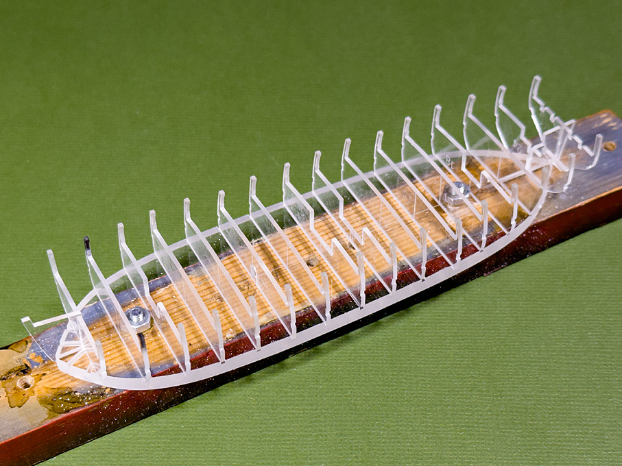
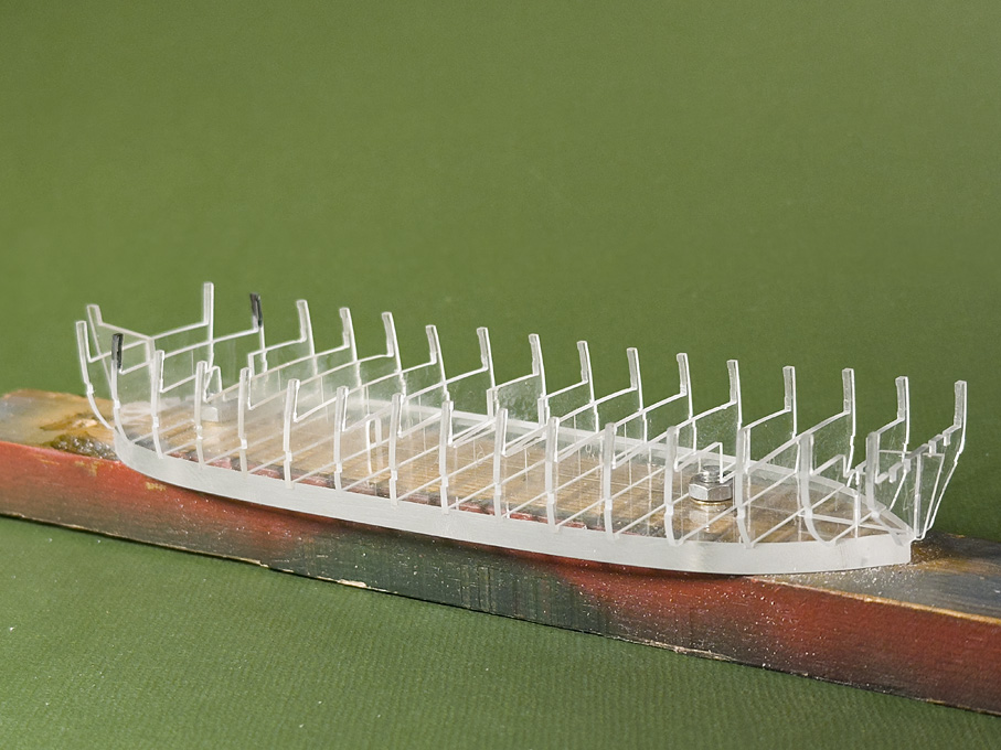
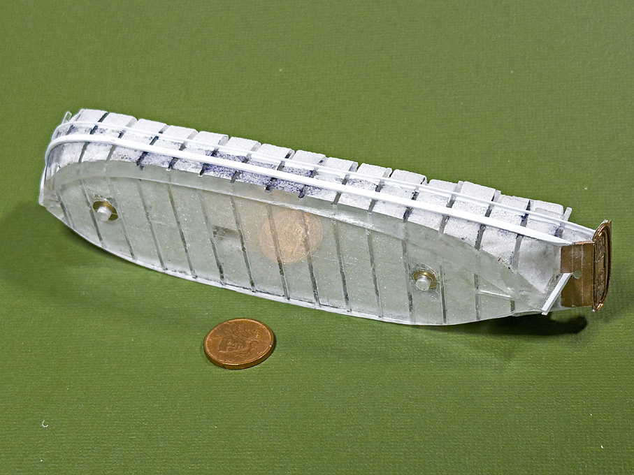
After careful checking, the bulkheads were now cemented in place with Acrifix 192�, which is essentially liquid, unpolimerised Plexiglas�. This basically unifies two pieces with the same material, resulting in a virtually indestructible bond. Together with the tight fit in the milled slots, a very rigid framework resulted.
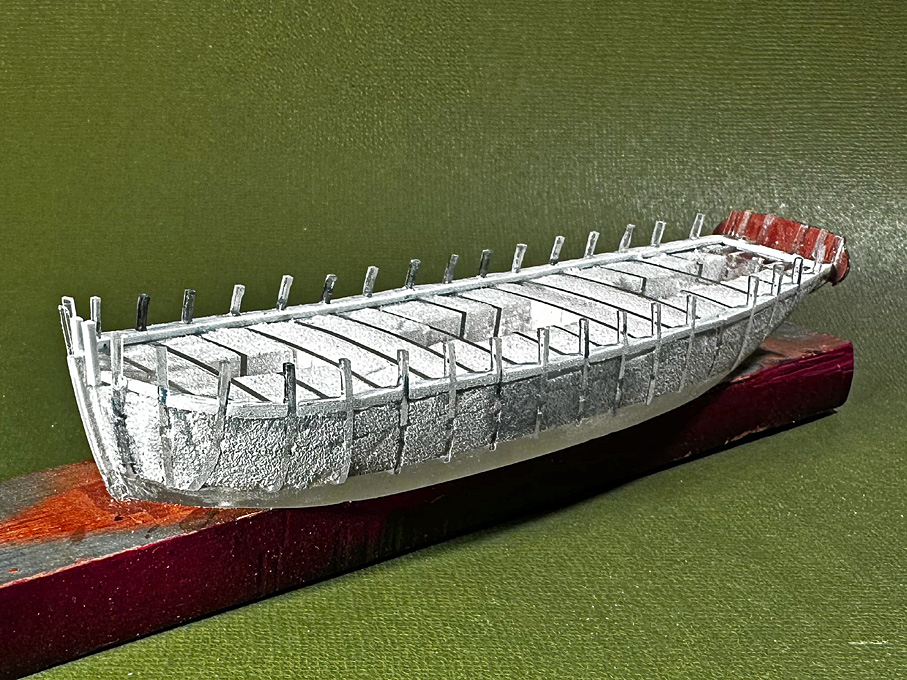
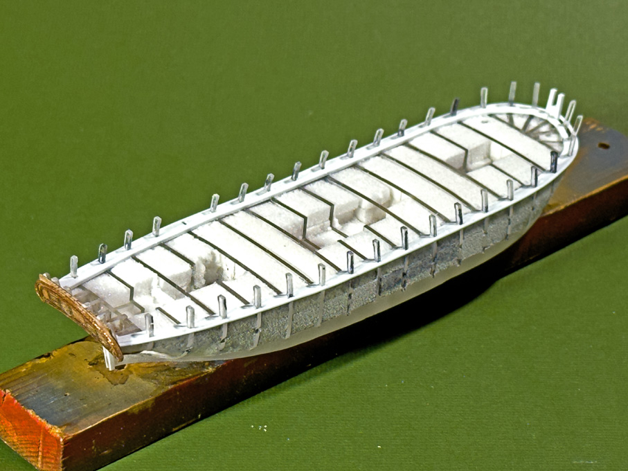
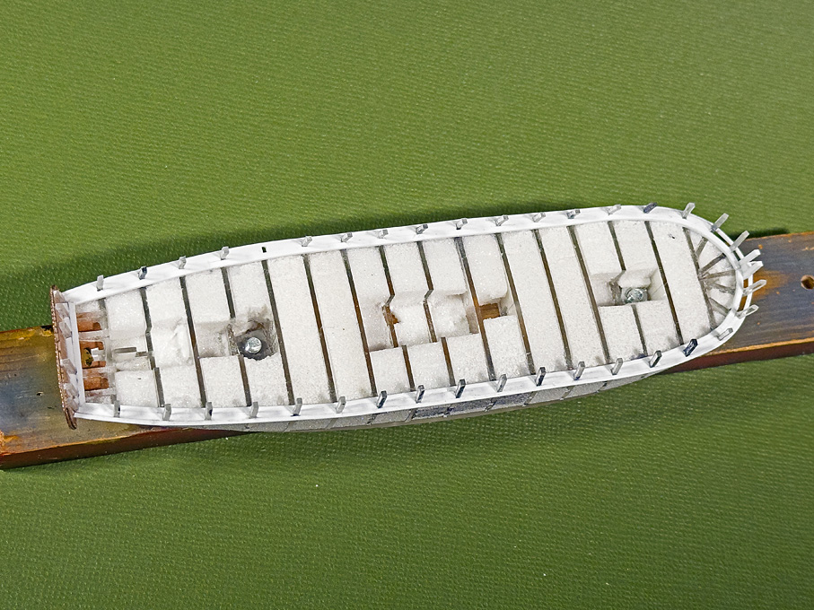
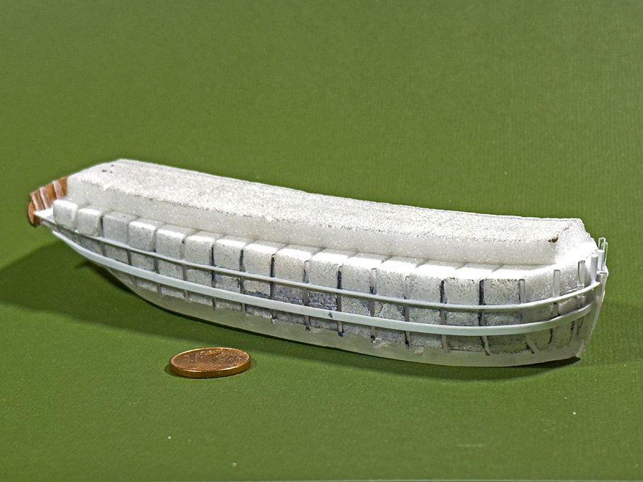
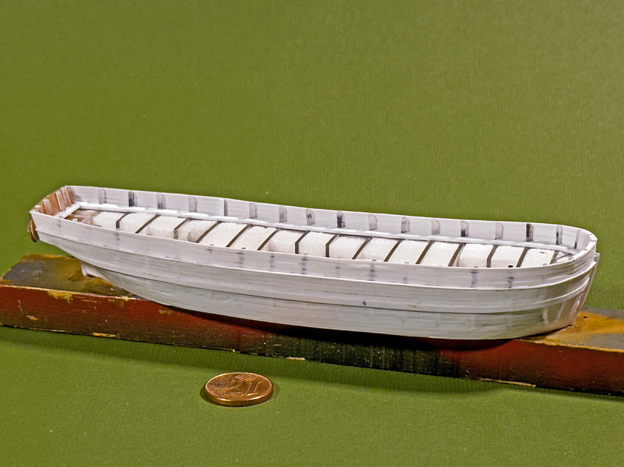
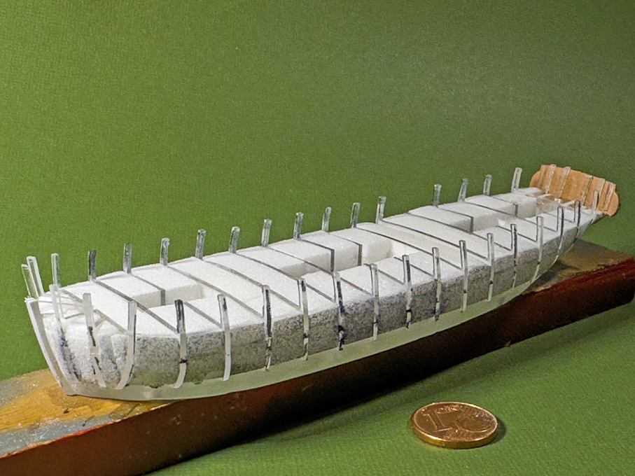
In order to facilitate fairing the bulkheads and prevent the very thin and flexible planking with styrene strips from sagging in, the space between them was filled with Rohacell� foam-board (
https://history.evonik.com/en/inventions/rohacell), which is an acrylic equivalent to Styrofoam, but much harder and finer grained. I actually used material left over from the first project I built this way back in the early 1980s. It is sufficient to glue the pieces in place with general purpose glue.
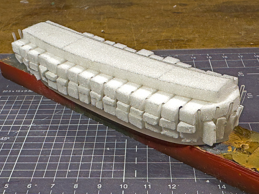 Spaces between the bulkheads filled with Rohacell� foam-board
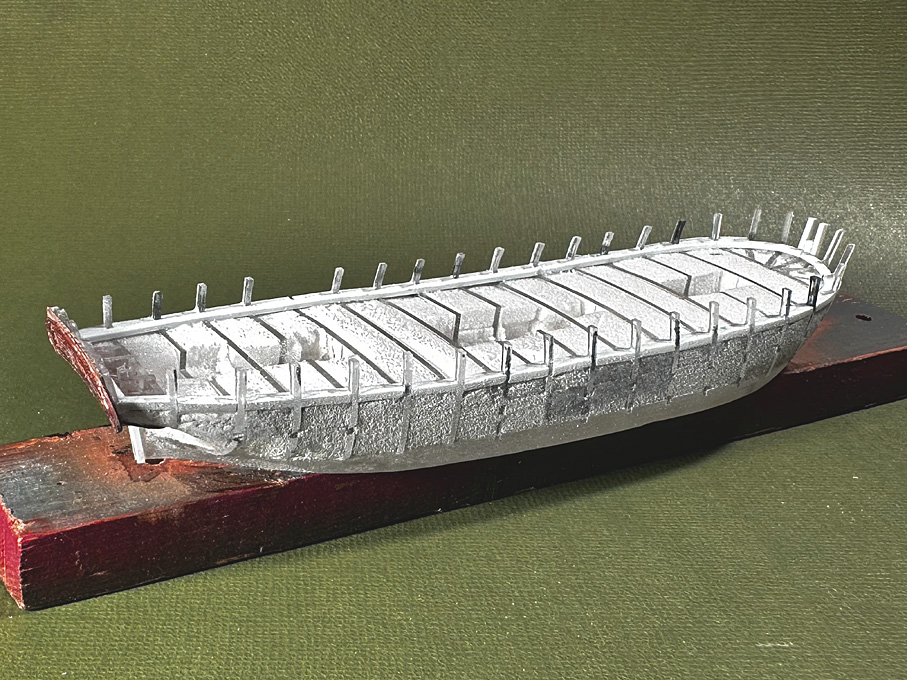
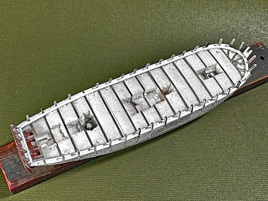
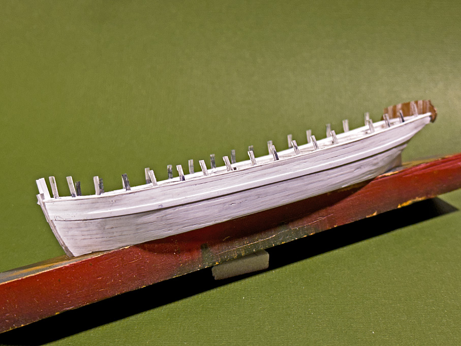
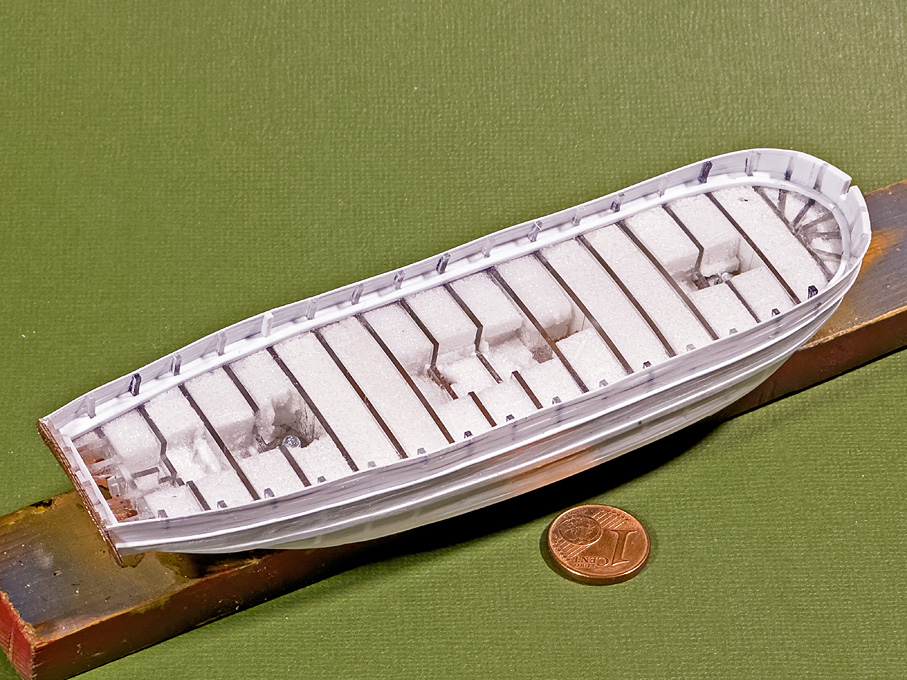
The bulwark stanchions are actually very fragile and to support them during fairing and being able to turn over the hull, the spaces between them were also filled with Rohacell�, but this unit was not glued down to the rest. Unfortunately, I still managed to snap one stanchion � Grrr.
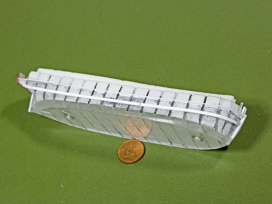
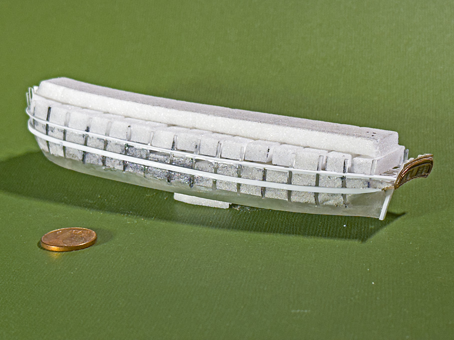
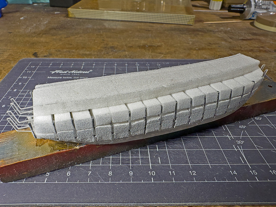 Spaces between the bulkhead filled with Rohacell� foam-board
The fillers were ground back to the bulkheads, the edges of which were blackened with a permanent marker to indicate when I touched them. I then progressed to fair the bulkheads.
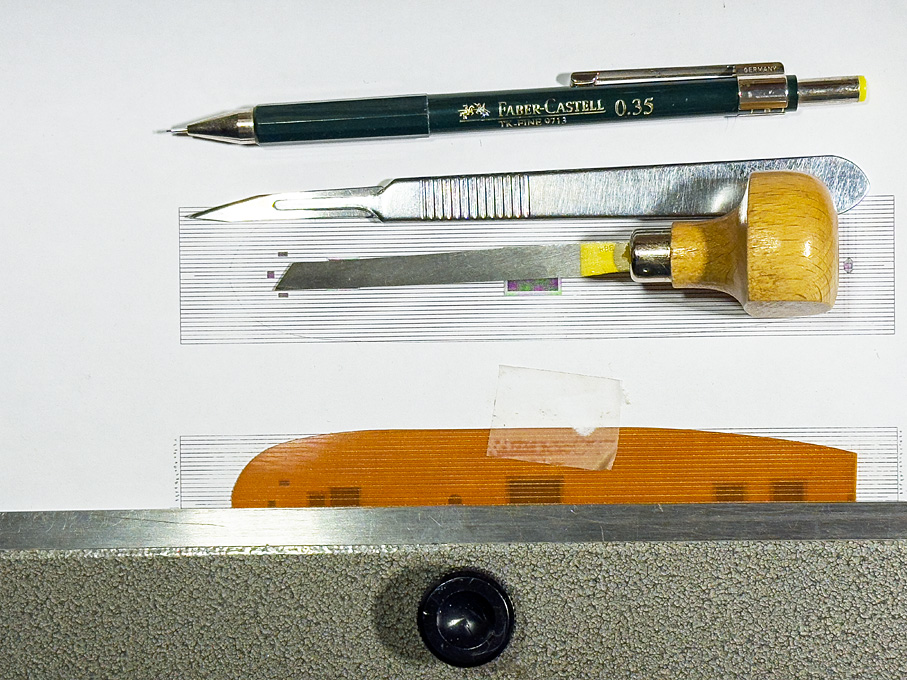
In the meantime, also pieces for the gill and the transom were drawn and laser-cut from Canson-paper and then soaked in zapon-varnish. At time when this ship was built, transoms often had carved elements and false windows, low-relief pilasters etc. as indicated in the original drawing. These were built up in two layers on a backing layer. Carved profiles were imitated with thin wire glued into place. The gill was also built up in three layers.
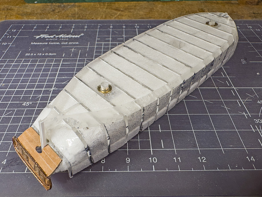 Looking up through the Plexiglas bottom-plate
When I offered up the gill piece to the �counter timbers� and checked, how the hull planking would run up against it, I realised that something was wrong. The last bulkhead was too full in the lower part, but completely conformed with the line in the original drawings. After some head-scratching and careful analysis of all the lines in the original drawings, it dawned on me that, while the rearmost frame was projected into the same plane as the other frames, it was in fact the profile of a cant-frame the trace of which was drawn onto the waterline-drawing. Some rough lofting confirmed that suspicion.
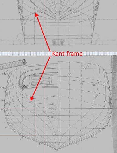 Extract from the original drawings with the misconceived cant-frames marked
There was no way of breaking off the faulty bulkhead due to the strong bond mentioned above. I had to shape the counter as is done in bread-and-butter construction. In fact, it might have been better to build up this area of complex curves from layers of Plexiglas right away. This kind of ships� counters are not so easy to deduct from the lines drawings and to understand in its complex geometry � at least not, if you are not a trained naval architect.
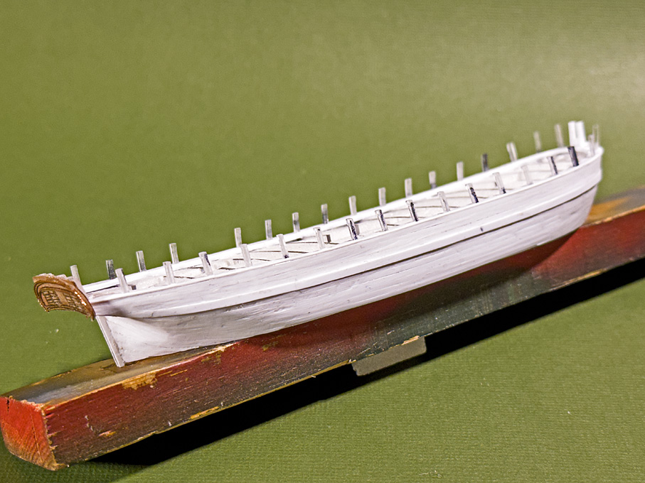
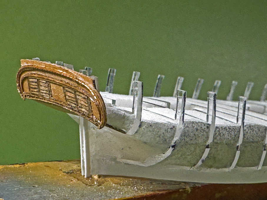
 The correctly shaped counter and ornate transom
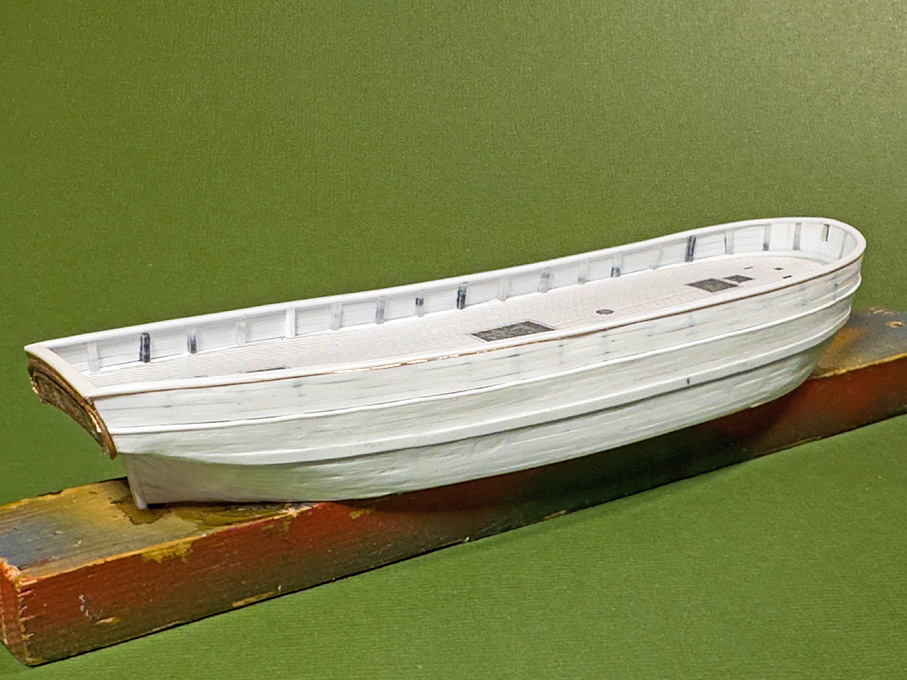
With the help of diamond burrs and files I managed to arrive at reasonable �free-form� representation of the stern and trust that eventually the construction mistake will not be visible. After these corrections the gill-piece and the transom were glued into place.
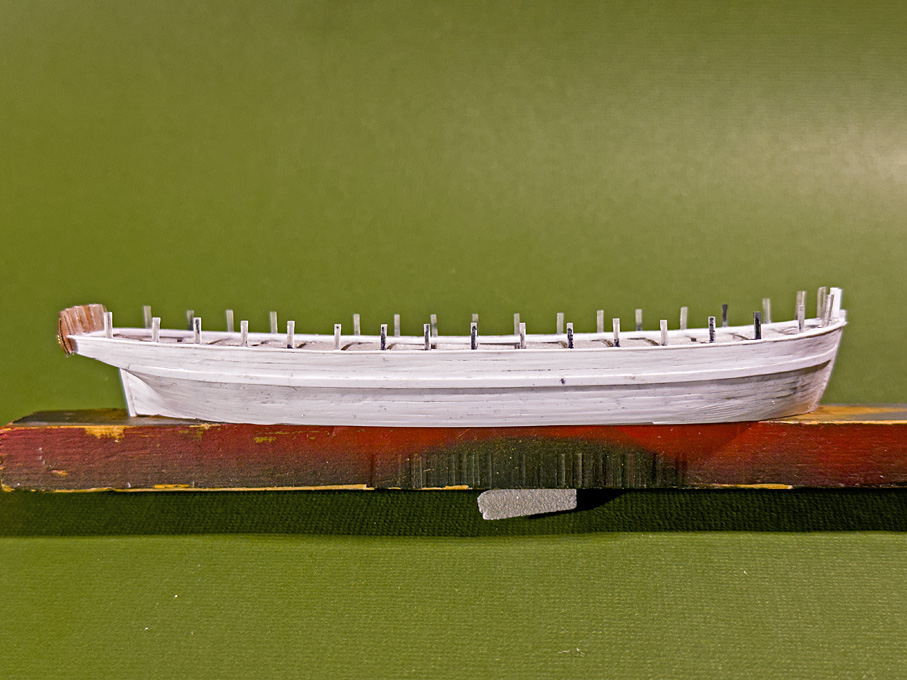
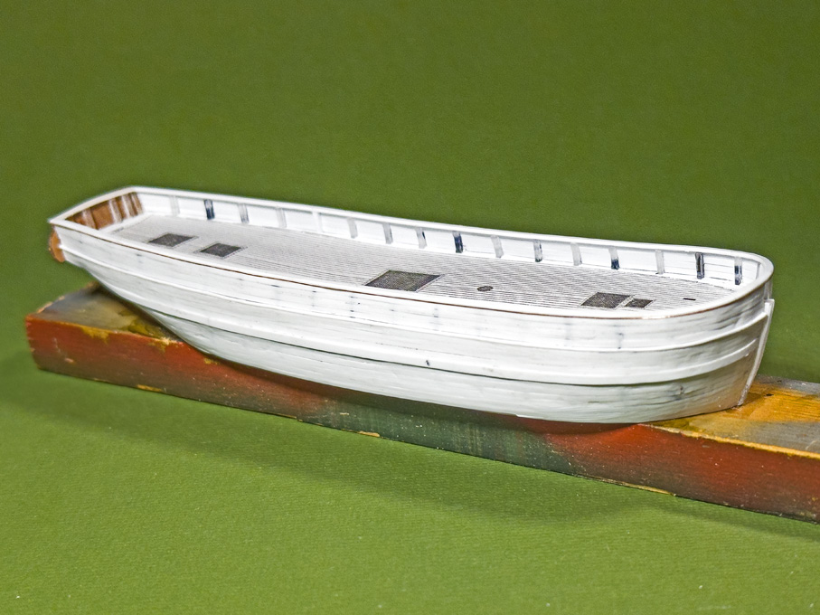
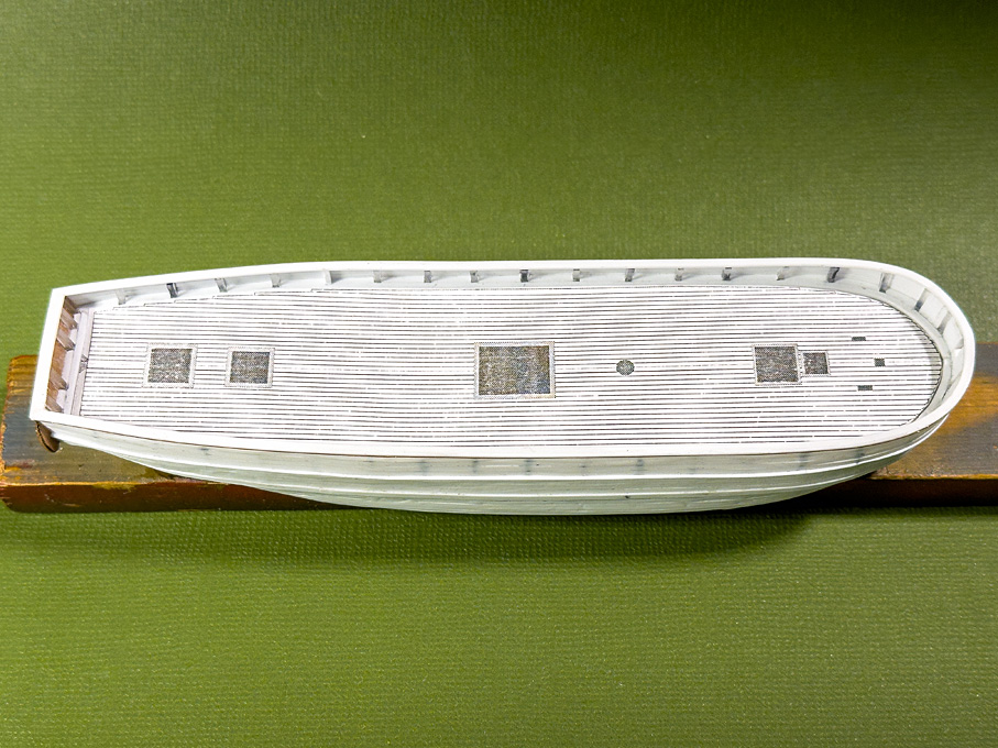
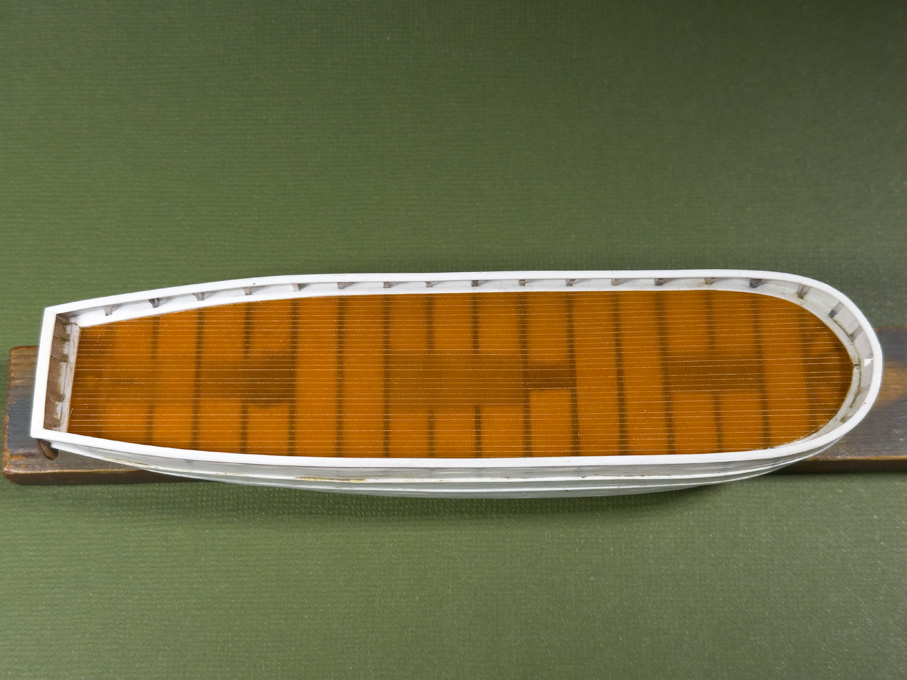
 Bow view of the hull ready for the planking layout
Admittedly this looks rather rough at this stage �
To be continued