In the PacFront models suggestion thread Jim Baumann makes an interesting remark about PE cagemast qouted below. I think this subject deserves its own thread. When I was still trying to build an early US Dreadnought (Arizona conversion from the Revells 1/720 kit) some 5 years ago I ran into similar problems. While the Tom's modelworks cage masts can become slighty more hourglass like as it includes a short part which can be put on top the result is still not very convincing. I traced the problem back to the fact that the gluing edges of the PE mast are straight. This may makes the result always a conical structure and not the semi- parabolic structure of the original. Cutting a very shallow semi-circle on both edges of the PE cage gave me lots of trouble as I either lost alignment of the cage "squares" or glueing surface. After ruining two PE sets I gave up and started doing japanese predreads. I do think that a better PE design, with semi circle or parabolic gluing edges may be the key to a more convincing cage masts. And if someone produces them I will buy at least one for my next american armoured cruiser - the one presently on order will become Pennsylvania in 1910.
What do you guys think?
>Jim baumann wrote<
Cage masts... I feel a PE design re-think is needed
To get the hourglass shape-or an approximation thereof--the mast PE could perhaps be done in sections-perhaps joined at the platform levels.
This certainly would avoid the 'Cone' look of most hitherto available cage masts in PE
Worth a thought? -- maybe offer the masts as a generic item separately?
Certainly worth getting the very best and finest PE etching done for that aspect!!
Cagemast PE
Moderator: JIM BAUMANN
-
Pieter
- Posts: 1608
- Joined: Sat Sep 17, 2005 9:19 am
Cagemast PE
Last edited by Pieter on Tue Nov 06, 2012 7:42 am, edited 1 time in total.
-
Andy G

- Posts: 234
- Joined: Wed Nov 02, 2005 9:12 am
Re: Cagemast PE
No flat fret is ever going to take a hyperboloid shape like a cage mast.
Yet you can form a hyperboloidal surface from straight edges and supporting rings. See here:

(Think about twisting a cylinder - it'll start to pinch in the middle, and the profile, between being 'parallel-sided' and 'two cones', will form the surface of a hyperboloid.)
Jim, and all - I've never used photoetch, and can't imagine working at these scales, but would some kind of jig, etched hoops and strips, and CA be feasible?
Andy
Yet you can form a hyperboloidal surface from straight edges and supporting rings. See here:
(Think about twisting a cylinder - it'll start to pinch in the middle, and the profile, between being 'parallel-sided' and 'two cones', will form the surface of a hyperboloid.)
Jim, and all - I've never used photoetch, and can't imagine working at these scales, but would some kind of jig, etched hoops and strips, and CA be feasible?
Andy
-
Foeth
-
Rob

- Posts: 1067
- Joined: Fri Jan 14, 2005 10:08 am
- Location: Cornwall
- Contact:
-
JIM BAUMANN

- Posts: 5689
- Joined: Mon Jan 10, 2005 5:30 pm
- Location: Nr Southampton England
Hi Guys
This is a worthwhile subject...
I have given it some thought also-obviously doing it the proper way is the only REAL way= although how succesfull and/or fine the result would be in 1/700.... hmmmnnn!
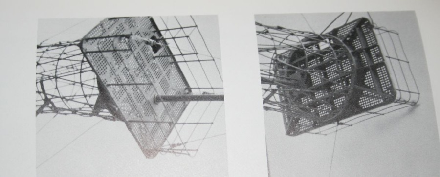
Here is an image of a 'proper ' 1/700 cage mast-courtesy of MW'er Alex Mandel -- BB30 USS Florida
The comments below--interesting --were copy/pasted from Steelnavy
Jon Warneke ( of ISW) is the author-(he has quoted me BTW..!)
Cage masts... I feel a PE design re-think
: is needed
:
: To get the hourglass shape-or an
: approximation thereof--the mast PE could
: perhaps be done in sections-perhaps joined
: at the platform levels.
:
: This certainly would avoid the 'Cone' look
: of most hitherto available cage masts in PE
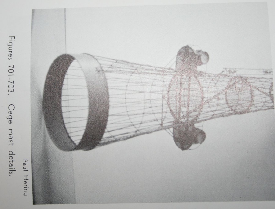
Unfortunately, as Bradford has mentioned, it isn't possible to make this in p/e. Here's why. The shape of a cage mast is, in technical terms, a elliptic hyperboloid of one sheet. It's a three dimensional structure that, by definition, can't be a two dimensional drawing. Your idea of a two-piece mast has the same problem, since it would be an elliptic hyperboloid of two sheets, and as such is also a three dimensional structure which can't be two dimensional. This was investigated when Jim Corley and I tried to design a proper cage mast for our pre-dreadnought kits, and that included your idea of a two-part mast. A two dimensional sheet of brass can only produce truncated cones. The look of the cage mast is the product of the height, diameter of the top and bottom circles, and rotation of the vertical members (US masts had a member rotation of 90 degrees). The only way to get a proper looking cage mast is to build it as the original was.
Jon
Jim Corley and I did come up with a "proper" elliptic hyperboloid for a model, in theory, but it would be somewhat impractical for the average modeler. Here's the description:
Create two cones of the proper height for the mast, one wiht the proper upper and lower diameter rings, and one with upper and lower rings smaller to allow for the thickness of the brass used. Both of these cones would have the correct number of vertical members for the specific design of mast. Roll both into a cone, then rotate the top of one clockwise 90 degrees, and rotate the other's top 90 degrees counterclockwise. This will give the part the correct elliptic hyperboloid shape, and by inserting the smaller one inside the larger, that will provide the correct design of the inner and outer segments of the mast. Rings would be included to slip over the outer piece at the correct location of attachment points, and you have a correctly designed elliptic hyperboloid cage mast.
The problem is getting the two cones rotated 90 degrees. You could design a jig that would hold the cone, and rotate the top while keeping the base fixed, but the members would probably not be rigid enough for the cone to hold it's shape. This is just one of the many problems we came up with designing a elliptic hyperboloid cage mast. But, we did come up with an idea...
Jon
This is a worthwhile subject...
I have given it some thought also-obviously doing it the proper way is the only REAL way= although how succesfull and/or fine the result would be in 1/700.... hmmmnnn!
Here is an image of a 'proper ' 1/700 cage mast-courtesy of MW'er Alex Mandel -- BB30 USS Florida
The comments below--interesting --were copy/pasted from Steelnavy
Jon Warneke ( of ISW) is the author-(he has quoted me BTW..!)
Cage masts... I feel a PE design re-think
: is needed
:
: To get the hourglass shape-or an
: approximation thereof--the mast PE could
: perhaps be done in sections-perhaps joined
: at the platform levels.
:
: This certainly would avoid the 'Cone' look
: of most hitherto available cage masts in PE
Unfortunately, as Bradford has mentioned, it isn't possible to make this in p/e. Here's why. The shape of a cage mast is, in technical terms, a elliptic hyperboloid of one sheet. It's a three dimensional structure that, by definition, can't be a two dimensional drawing. Your idea of a two-piece mast has the same problem, since it would be an elliptic hyperboloid of two sheets, and as such is also a three dimensional structure which can't be two dimensional. This was investigated when Jim Corley and I tried to design a proper cage mast for our pre-dreadnought kits, and that included your idea of a two-part mast. A two dimensional sheet of brass can only produce truncated cones. The look of the cage mast is the product of the height, diameter of the top and bottom circles, and rotation of the vertical members (US masts had a member rotation of 90 degrees). The only way to get a proper looking cage mast is to build it as the original was.
Jon
Jim Corley and I did come up with a "proper" elliptic hyperboloid for a model, in theory, but it would be somewhat impractical for the average modeler. Here's the description:
Create two cones of the proper height for the mast, one wiht the proper upper and lower diameter rings, and one with upper and lower rings smaller to allow for the thickness of the brass used. Both of these cones would have the correct number of vertical members for the specific design of mast. Roll both into a cone, then rotate the top of one clockwise 90 degrees, and rotate the other's top 90 degrees counterclockwise. This will give the part the correct elliptic hyperboloid shape, and by inserting the smaller one inside the larger, that will provide the correct design of the inner and outer segments of the mast. Rings would be included to slip over the outer piece at the correct location of attachment points, and you have a correctly designed elliptic hyperboloid cage mast.
The problem is getting the two cones rotated 90 degrees. You could design a jig that would hold the cone, and rotate the top while keeping the base fixed, but the members would probably not be rigid enough for the cone to hold it's shape. This is just one of the many problems we came up with designing a elliptic hyperboloid cage mast. But, we did come up with an idea...
Jon
Last edited by JIM BAUMANN on Fri May 11, 2007 2:48 pm, edited 1 time in total.
....I buy them at three times the speed I build 'em.... will I live long enough to empty my stash...?
http://www.modelshipgallery.com/gallery ... index.html
IPMS UK SIG (special interest group) www.finewaterline.com
http://www.modelshipgallery.com/gallery ... index.html
IPMS UK SIG (special interest group) www.finewaterline.com
-
JIM BAUMANN
- Posts: 5689
- Joined: Mon Jan 10, 2005 5:30 pm
- Location: Nr Southampton England
That fine old book--BUILDING WARSHIP MODELS by
P C Coker III
has some interesting ideas and methodolgy
see scans below
JIM B
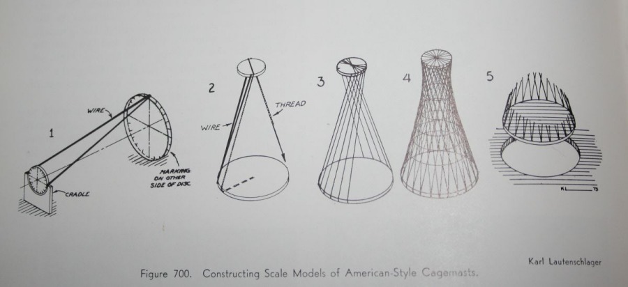
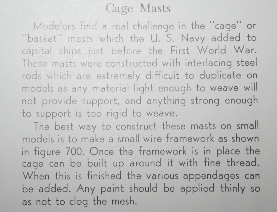

[im
P C Coker III
has some interesting ideas and methodolgy
see scans below
JIM B
[im
....I buy them at three times the speed I build 'em.... will I live long enough to empty my stash...?
http://www.modelshipgallery.com/gallery ... index.html
IPMS UK SIG (special interest group) www.finewaterline.com
http://www.modelshipgallery.com/gallery ... index.html
IPMS UK SIG (special interest group) www.finewaterline.com
-
chuck

- Posts: 3384
- Joined: Mon Jan 10, 2005 1:21 pm
- Location: equidistant to everywhere
It shouldn't be that hardEJ Foeth wrote:You need to make to jigs and something to space them (a tube, so you can bolt both jist to the tube). The jigs need to have a huge number of holes. Next, loop a brass wire through all the hoops. When done, solder ALL joints, cut and enjoy. Not so easy as it sounds, I guess.
You need 2 parallel plates separated by a connecting rod so they are as far apart as the cage mast is long. Drill a ring of wholes in each plate so that the diameter of the ring is equal in diameter to the base and top of the cage mast, with each ring having half as many holes as there are vertical ribs in the mast. Insert wires through the holes in the bottom plate and ensure they emerge through a hole in top plate that is several holes further along the ring than where they went through the bottom plate. When you've completed one around, turn around and go back the other direction by adding another set of wires, except this time threaded it through the top plate hole that is the same number of holes further back along the ring than where they went through the bottom. When all is done, solder or glue where the wires cross, and you've got a rudimentary hyperbloid cage mast. If you want horizontal reinforcement bands you should either solder them on afterwards, or else you have to expand the jig to include them at the onset. But their distance and spacing require some experimentation.
-
JHS
- Posts: 230
- Joined: Tue Nov 14, 2006 9:29 pm
From looking at that FLORIDA model in 1:700, it appears as if the need for wire geodetic masts in this tiny scale is actually a luxury for the specialists. I'd be very happy with resin masts with scale "wires" and of the correct shape. I found the phony photoetch geodetic masts on the Hi-Mold American dreadnoughts with their way off shape spoiled the models for me.
-
chuck
- Posts: 3384
- Joined: Mon Jan 10, 2005 1:21 pm
- Location: equidistant to everywhere
-
Pieter
- Posts: 1608
- Joined: Sat Sep 17, 2005 9:19 am
I've been away for a few days so I'm just catching up here.
Chuck's suggestion is actually Tom's modelworks approach, or at least the combination of a long cone and a short cone included in his PE sets can have this result. I also think Sami Arim's short lived PE efforts in 1/1200 had the same approach. It may just have been Tom's intention however to include the neccesary masts for a California class battleship at Pearl Harbor.
I've been looking at some of the diagrams here in this thread and I think that the main problem with my original suggestion will be the widening of the cage mast shape towards the top. A two part approach with a middle circle (remember most cagemasts had a stiffening ring at the thinnest point circle anyway) and a slight curve in both glueing edges should give you a good approximation of a Rhomboid shape. It will not be mathematically perfect but when was the last time you planned a 100km road trip on a globe instead of on a map? The difference will hardly be visible while the straight lines of the cone shape use currently are visible as humans have a a tendency to spot and over emphasize straight lines (this is also a problem with porthole pattern mistakes on liner kits). And using a cast resin shape instead of a cage mast in 1/700.... let's say I built using different standards and I am far, far away from the expert level of people like Jim Baumann and Alex Mandel. If you're using PE catapults and railings you should also use PE cage masts.
[quote="chuck"]Perhaps PE makers can make a better shaped cage mast by dividing the mast lengthwise into sections, and for each section providing PE that would roll up into a truncated cone of an appropriate angle. These truncated cones with different angles can then stack together to simulate a hyperboloid cage?[/quote]
-
john bange
- Posts: 36
- Joined: Mon Jan 23, 2006 9:56 pm
- Location: seattle, wa.
-
JIM BAUMANN
- Posts: 5689
- Joined: Mon Jan 10, 2005 5:30 pm
- Location: Nr Southampton England
THERE is a whole chapter of his models in this very worthwhile book
Warship Models by John Bowen--get your copy here for under $ 10.00...
http://www.abebooks.com/servlet/SearchR ... &y=13&x=47
Warship Models by John Bowen--get your copy here for under $ 10.00...
http://www.abebooks.com/servlet/SearchR ... &y=13&x=47
....I buy them at three times the speed I build 'em.... will I live long enough to empty my stash...?
http://www.modelshipgallery.com/gallery ... index.html
IPMS UK SIG (special interest group) www.finewaterline.com
http://www.modelshipgallery.com/gallery ... index.html
IPMS UK SIG (special interest group) www.finewaterline.com
-
john bange
- Posts: 36
- Joined: Mon Jan 23, 2006 9:56 pm
- Location: seattle, wa.
-
SeanF
- Posts: 798
- Joined: Wed Nov 02, 2005 10:28 pm
- Location: Downey, California
I think the best compromise possible in photoetch would be a three-piece assembly. From studying the Arizona's as-completed cagemast, I see that the lower half contains twice as many rods as the upper half, and the upper half is essentially symmetrical mirrored across the 3/4 height line. Thus, I suggest three conical pieces with the upper two quarters identical and joined narrow end to narrow end, and then glued atop the lower half. Not a smooth curve, obviously, but a heck of a lot closer to the real shape than a straight cone all the way up. (Some rolling templates would be nice, too.) In 1:700 scale it should be effective enough, especially after platforms are added.
Not all cage masts are made the same, though. The Arisona's cage is heavier than the ones fitted to the South Carolinas and pre-dreads, but nowhere near as heavy as the ones on the Tennessee and Colorado classes (and intended for the Lexingtons and South Dakotas), with their big tops. Different PE sets would be in order for the different cases.
Also, regarding the Colorado in today's gallery update: Looks great, but not a good example for the wider cage mast discussion. The segment of cage remaining in the late war Colorado and Maryland is so short it shows almost no curvature in photos. (The sides almost looks purely vertical, in fact.)
- Sean F.
-
Alex Mandel
- Posts: 25
- Joined: Wed Jan 03, 2007 9:54 am
- Location: Ukraine
Dear Colleagues in Modelism,
Thank you very much for sharing your most interesting comments on this "notorious problem" that the US caged masts certainly are for a modeler!
The graphic explanation of Andy G. "what this mast really is" is just on target, and very illustrative... and the scans from the P C Coker III's book "BUILDING WARSHIP MODELS", posted by Jim Baumann, are really excellent.
I'm afraid, it really represents the "only existing way" to imitate such a mast really "properly" (as a hyperboloid, not a cone-looking). And, actually, it is exactly how i built the caged mast for my 1:700 US Florida, and then 2 such masts for the 1:720 USS Colorado - that i am currently "converting" from the old good Revell's 1:720 Arizona.
The ship will be in her 30s appearance - with a "short" caged foremast (because of the lower - bigger - part of it was already "absorbed" by a forward superstructure, as we remember), and with a "full height" caged mainmast.
The ship is still quite far from being really completed yet... but both masts are already on their places. So, i will try in a day or two to photograph it, and will send these photos to the Forum... I will try to photograph it in such a way for to make the "structure" of the masts clearly visible... and hope maybe these pix will "illustrate the problem" in some useful way... Kind Regards to All! - very sincerely, Alex

-
JIM BAUMANN
- Posts: 5689
- Joined: Mon Jan 10, 2005 5:30 pm
- Location: Nr Southampton England
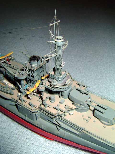
Alex Mandel has asked me to post these 'in-progress' pictures of his new model .
"Here goes some photos of my 1:720 USS Colorado, "converted" from the old good Revell's USS Arizona. It is pretty incomplete yet, with a lot of details still absent... but I thought maybe somebody will find it interesting or useful in aspect of this problem of imitating the US Navy caged masts.
Kind Regards - sincerely, Alex"
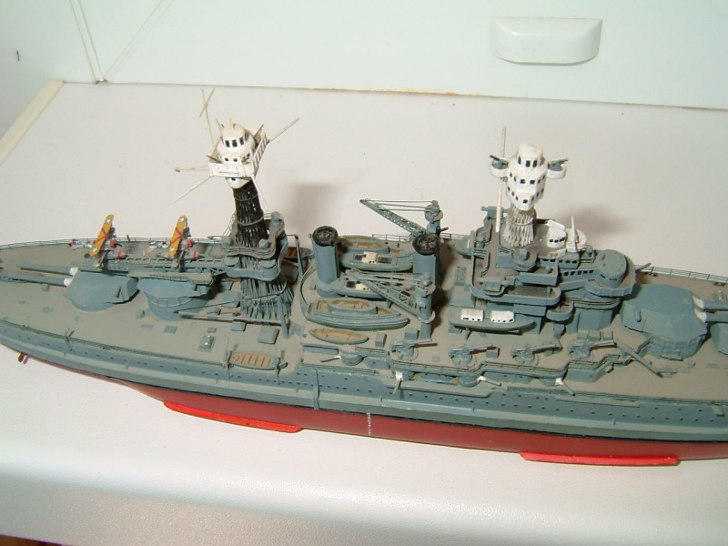
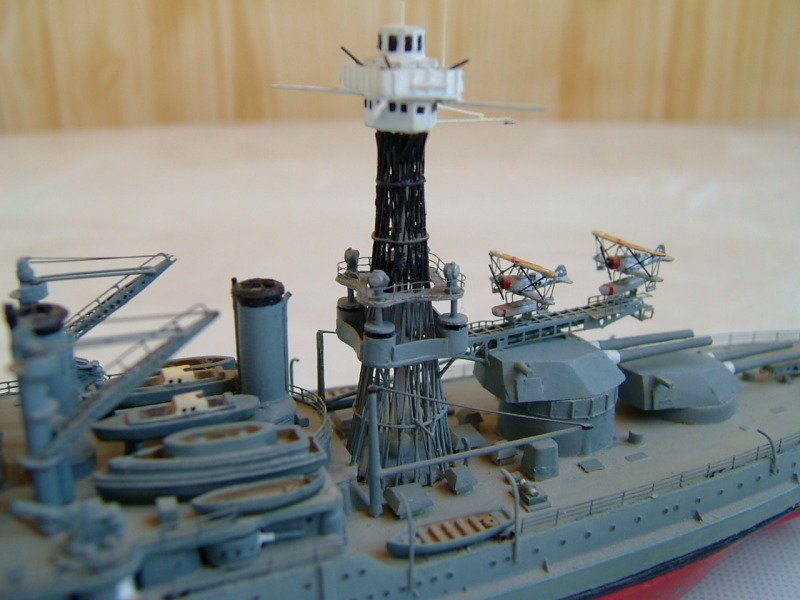
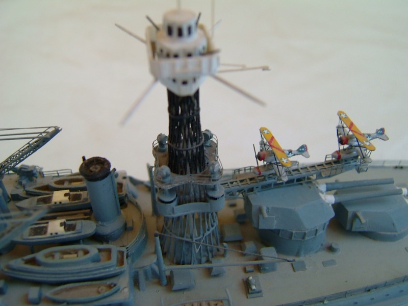
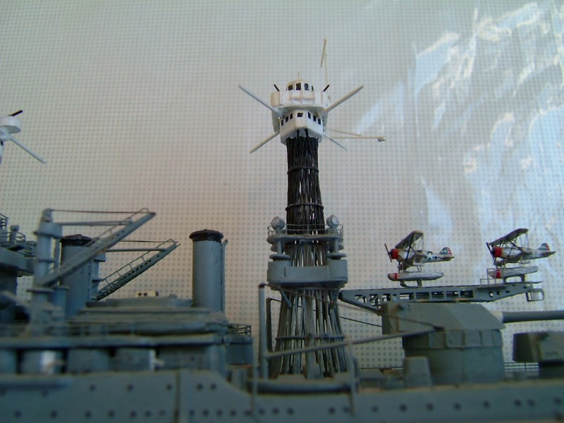
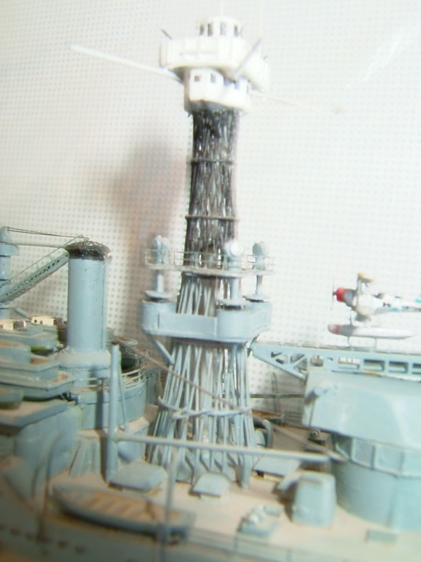
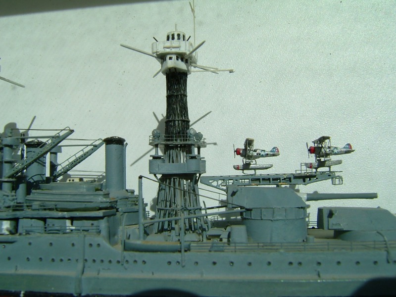
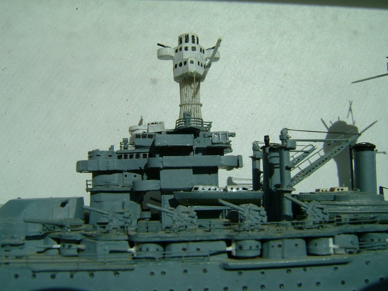
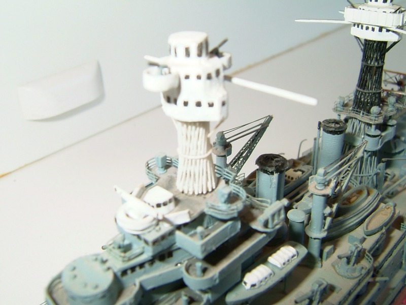
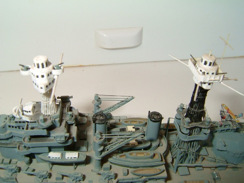
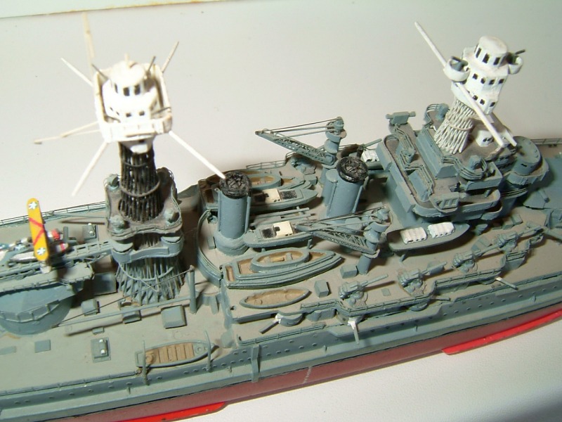
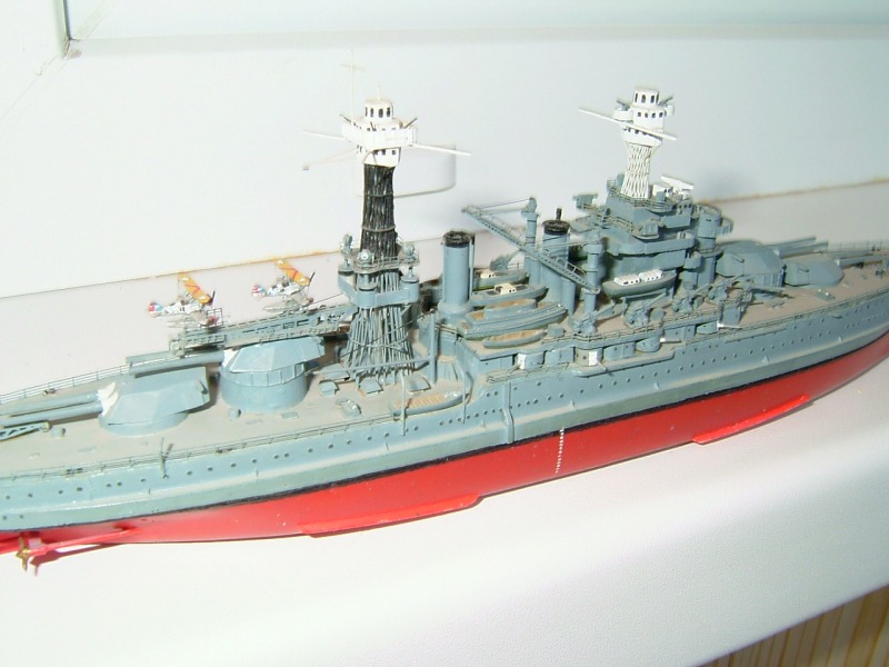
....I buy them at three times the speed I build 'em.... will I live long enough to empty my stash...?
http://www.modelshipgallery.com/gallery ... index.html
IPMS UK SIG (special interest group) www.finewaterline.com
http://www.modelshipgallery.com/gallery ... index.html
IPMS UK SIG (special interest group) www.finewaterline.com
-
john bange
- Posts: 36
- Joined: Mon Jan 23, 2006 9:56 pm
- Location: seattle, wa.