Some more deck details
There were some deck details of which the location puzzled me a bit. These included the down-pipes into the chain-locker for the anchor-chains (to be discussed later), the chimney(s) for the stove(s) in the crew- and captain’s quarters, the mandatory drinking-water barrel, and to some extent the bilge-pump (also to be discussed later).
Chimney
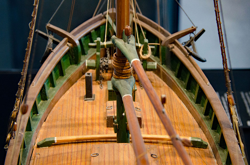
By the middle of the 19th century small cast-iron stoves were in common use on ships like the Rahschlup. Looking at illustrations of the time, the more traditional square, sheet-metal lined wooden chimneys were gradually replaced by round sheet-metal stove pipes. The chimney could be removed and the passage through the deck closed with a cap, so that they would not get in the way when handling the anchors or sails.
I found a good image in my collection of a model of a Jagt in the Museet for Søfart in Helsingør/Danmark, that shows exactly the sort of arrangement that I had in mind.
 Model of a Jagt in the Museet for Søfart in Helsingør/Danmark
Perhaps the best illustration of the interior arrangement is that of ‘Caboteur Danois’, i.e. a Danish ‘jagt’, from Paris’ ‘Souvenirs de la Marine’ (Planche 213). It gives even more details than the drawings for DE FIRE BRØDERE and CASTOR from Nielsen‘s ‚Danske Bådtyper‘.
According to this the stove in the crew quarters is placed next to the access ladder, at the rear bulkhead, while the placement of the one in the captain’s quarters depends on the layout of that cabin. Again, it is likely placed against the forward bulkhead.
 Caboteur Danois (jagt), Pl. 213 of the Souvenirs de la Marine by E. de Pâris
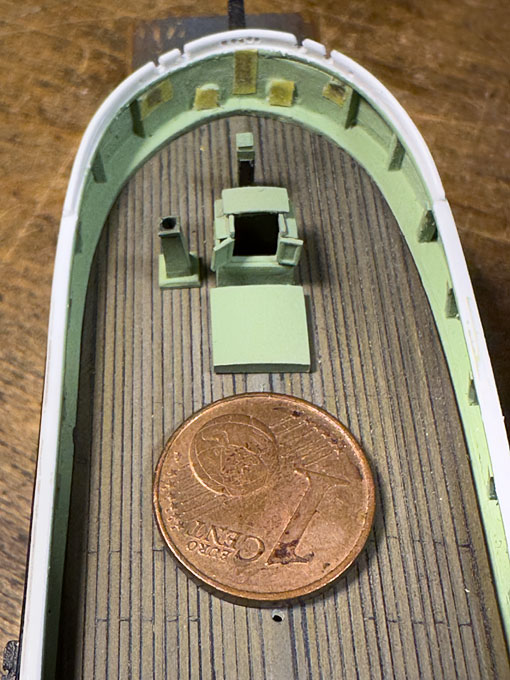
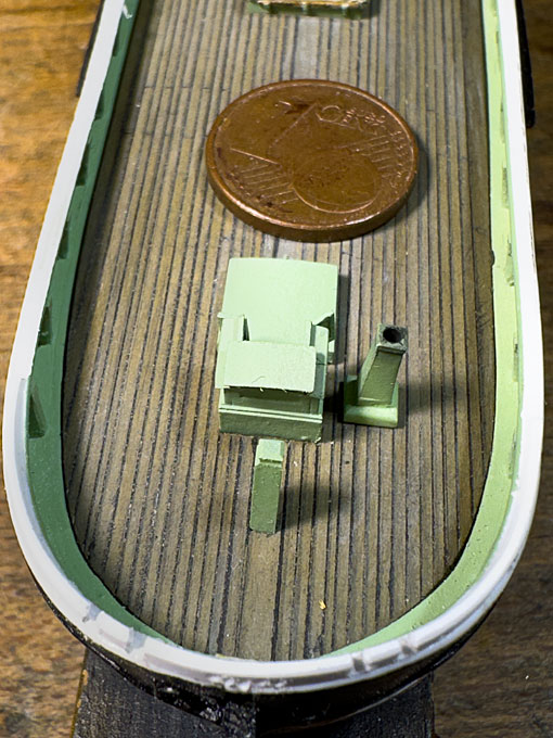
As the model will be shown moored alongside a quay, the chimney will be rigged and will be placed on the port side of the crew companionway. Although, I envisage a summer setting, it is shown, because the stove would have been used for cooking as well.
I am not sure, where the stove for the main cabin would have been placed, but I am showing it as closed with a cap on the port side of the companionway.
The forward chimney was milled from a piece of 2 mm x 2 mm polystyrene rod with the base as a separate piece cut from 1 nm x 3.2 mm polystyrene.
 Drinking-water barrel
According to pictorial evidence, the placement of the barrel was quite variable, probably at a place where it did not get in the way of the operation of the ship and where it was somewhat protected. Often it was placed near the bulwark or near a companionway. As there is quite a distance between the main cabin companionway and the main hatch, I put it in front of the companionway.
The barrel was turned from a length of 4 mm acrylic rod, giving a barrel of of about 60 cm diameter, which appeared about right according to photographs of the time. With a length of about 5 mm (= 80 cm) such a barrel would hold about 200 l, which should be sufficient for a few days for a crew of 5 to 6.
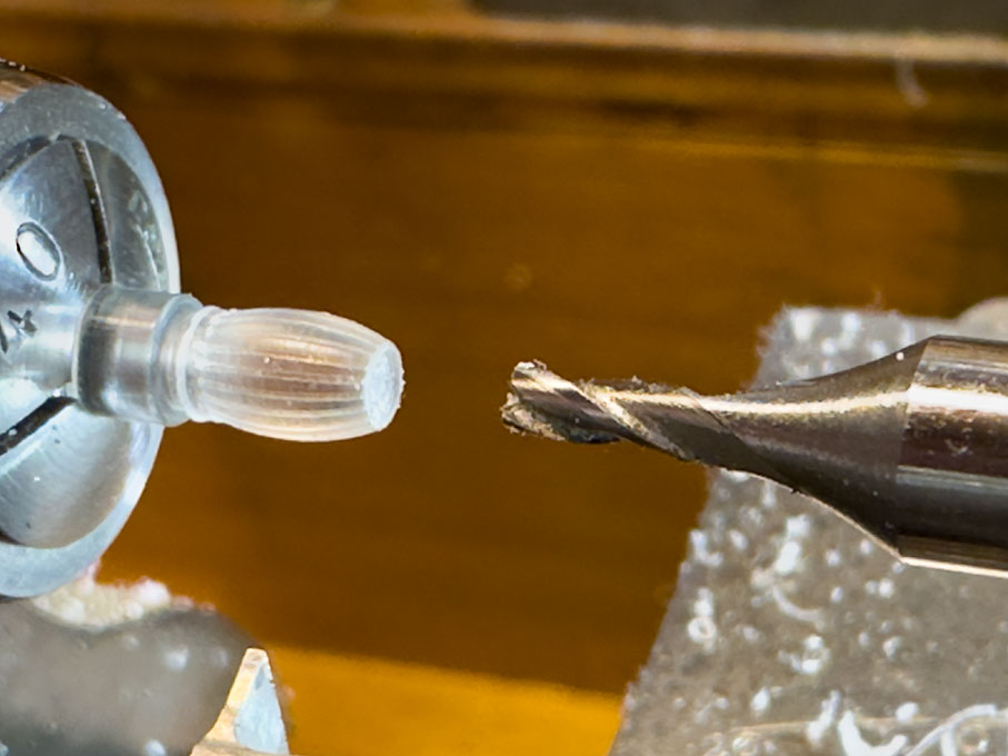
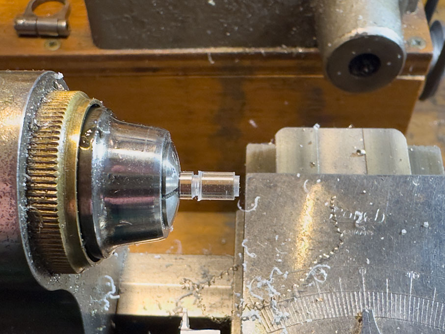 Determining the overall dimensions of the barrel
The curvature of the barrel was turned with the help of the radius turning attachment I made some years ago, held in the quick-change tool-post (QCTP). The geometries were worked out on my CAD software, i.e. the radius of the curvature was set to 9 mm and the minimum diameter would be 3 mm. Accordingly, a step with 3 mm diameter was turned on each side of the blank and then the attachment set to the middle of the future barrel. The whole radius turning tool was lowered in steps until the tool arrived at the minimum diameter.
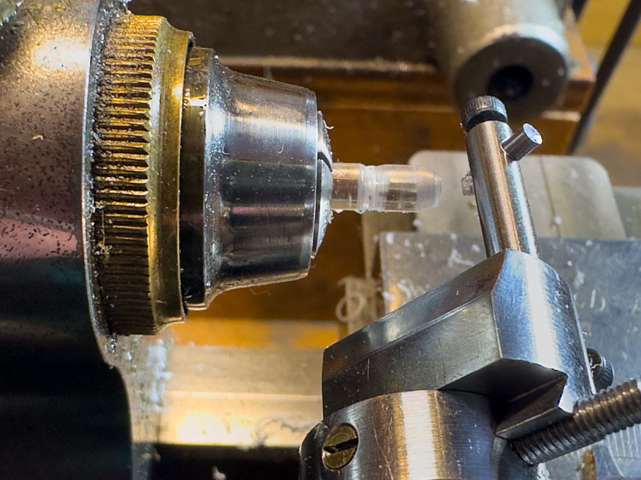 Initial steps of turning the curvature with the radius turning tool
 Final shape of the barrel
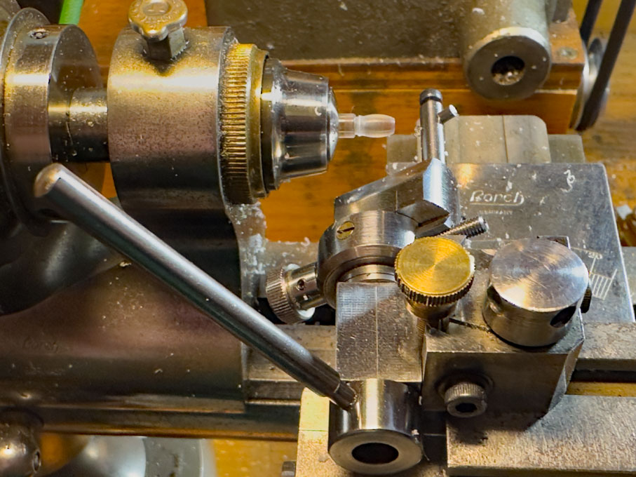
Without changing any other settings, the cutting tool was turned by 90° so that it cut lengthwise. The radius now was reduced by 0.1 mm to lightly engrave the staves. An Internet-consultation revealed that the staves should be about 10 cm wide at the large circumference. For a 60 cm diameter barrel this results in about 20 staves. Using the built-in dividing disc of the watchmakers lathe these 20 staves were engraved one by one.
 Engraving the staves
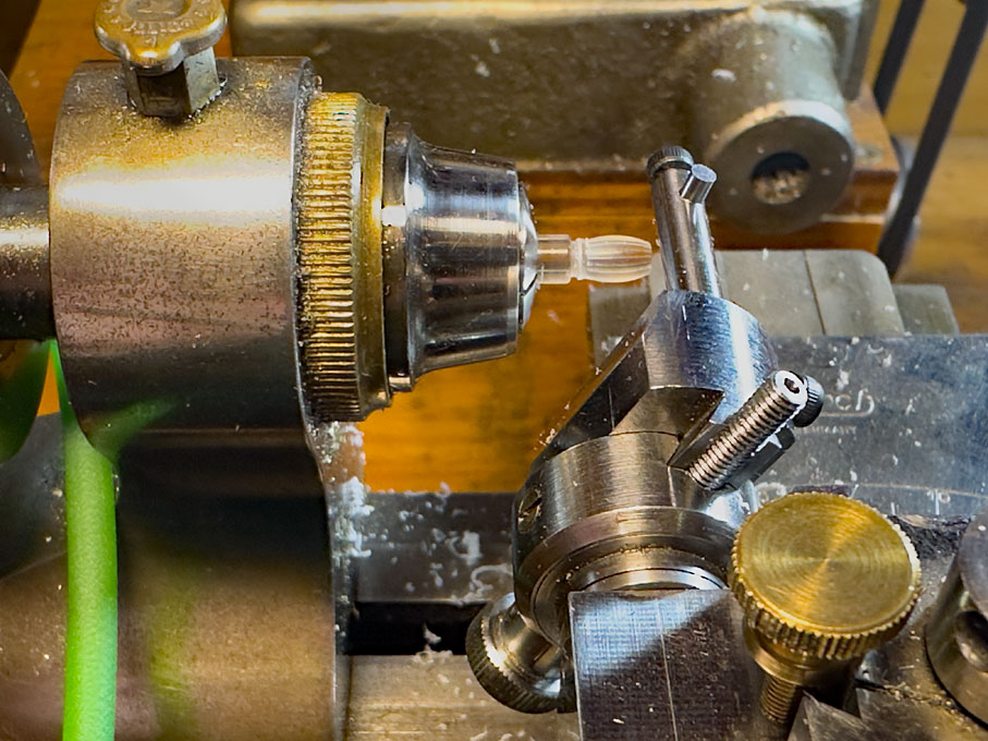
The recesses for the lids were simply cut with an end-mill that cuts over the centre. Holding the barrel once it has been parted off the stock was a bit tricky, but the watchmakers’ collets pinch at the front, so that even bulbous parts can be held for light operations.
 Cutting the recesses for the lids
The cradle was fabricated from tiny pieces of various polystyrene profiles.
Barrel and cradle were given a base-coat of the same green as the other deck furniture. The barrel-hoops and the retaining straps are thin pre-painted strips of paper.
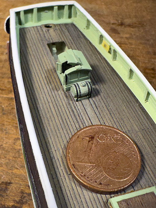 The painted water barrel at its future location
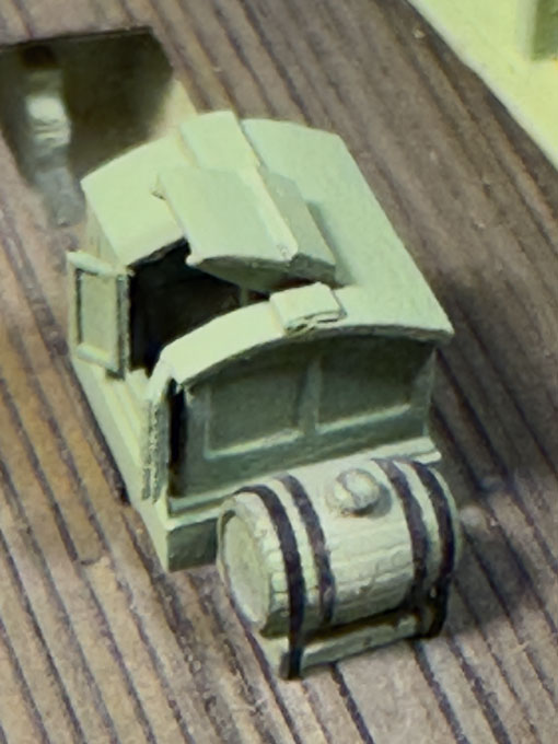 … and a horribly sobering close-up shot of the water barrel
To be continued …
… and a horribly sobering close-up shot of the water barrel
To be continued …