Ah thanks. That's an interesting book. Good drawings and photos, but somewhat questionable text.
I found this on p. 451 of the Skizzenbuch by Donald M. Prince:
Direction Finding � A rotating loop aerial, approximately 2 ft. 6 in. internal diameter and about 2 ft. clear of the bridge casing when fully extended, was fitted on the starboard side of the bridge and could be raised, lowered and rotated from inside the U-Boat. The feeder cable was run from this aerial to the W/T Radio Room (cabin No. 1) and could be connected to the M/F and L/F D/F receiver (see (b) (5) previous page). This aerial and receiver could be used for obtaining D/F observations and alternatively for under-water reception on the L/F range (15-33 kcs)
Jacob
Under Construction:
1/350 Typhoon
1/350 Skate
1/350 USS Nautilus
1/350 Tang
1/350 November
1/350 Hotel II
1/350 Alfa
1/350 George Washington
1/72 Type VIIC
Thanks. The skitzenbuch is very informative. Far far better than the Anatomy of the Ship volume on the VII and highlight numerous serious omissions in the latter reference,
Assessing the impact of new area rug under modeling table.
The midship ballast saddle tank venting pipes on either side of the conning tower are almost as prominent as the diesel air trunk and pressure hull air circulation trunks under the casing, but every other reference for details under the casing seems to have missed them.
Assessing the impact of new area rug under modeling table.
I'd suggest getting a copy of Vom Original zum Modell: Uboottyp VIIC by Fritz K�hl and Axel Niestle.
Jacob
Under Construction:
1/350 Typhoon
1/350 Skate
1/350 USS Nautilus
1/350 Tang
1/350 November
1/350 Hotel II
1/350 Alfa
1/350 George Washington
1/72 Type VIIC
it appears the prominent bulge on the port side of the conning tower that mid-war type VIIC usually have from around 1941 actually houses a massive extendable antenna mast whose shaft is the same diameter as the main shaft of one of the parascopes. It seems similar to the extendable antenna mast carried by early type IXC on the port side of their conning tower in the same position.
i found a clear photo of U-203 retuning to Lorient with this antenna mast extended.
yet i�ve found no references that mention this nor any drawings, including reproductions of original german plans, that show this on the VIIC, although many drawings of IXC shows this mast extended. revell missed it on their VIIC kit, giving only the option to extend a small jackstaff whip antenna out if this housing, although they too correctly showed the thick antenna mast option for their IXC kit.
Assessing the impact of new area rug under modeling table.
I'm not sure where you're looking, but many sources mention the rod aerial (stabantenne). It was a slim (maybe 1-2" diameter; definitely not the same diameter as a periscope) antenna for radio communications while at periscope depth. The antenna provided with the Revell kit appears to be reasonably accurate. It appears that the aerial for the Type IX was in some cases a much thicker mast, which I assume is what you're referring to.
When you're asking a question, please post photos/drawings so that we know what you're talking about. It's hard to tell you what you're seeing in the photo of the U-203 if we cannot also see that photo.
Under Construction:
1/350 Typhoon
1/350 Skate
1/350 USS Nautilus
1/350 Tang
1/350 November
1/350 Hotel II
1/350 Alfa
1/350 George Washington
1/72 Type VIIC
Vepr157 wrote:I'm not sure where you're looking, but many sources mention the rod aerial (stabantenne). It was a slim (maybe 1-2" diameter; definitely not the same diameter as a periscope) antenna for radio communications while at periscope depth. The antenna provided with the Revell kit appears to be reasonably accurate. It appears that the aerial for the Type IX was in some cases a much thicker mast, which I assume is what you're referring to.
When you're asking a question, please post photos/drawings so that we know what you're talking about. It's hard to tell you what you're seeing in the photo of the U-203 if we cannot also see that photo.
1st of all, I did not ask a question. I presented a piece of information.
I know many source mention and illustrate the small rod antenna. And revell depicts the rod antenna as so mentioned and illustrated. The small antenna always seem to me to be quite disproportionate to the large bulge on the side of the mid-war VIIC conning tower that accommodates it. The bulge is actually larger than the bulge on the side of thr IXC conning tower that is definitely there to accommodates a periscope shaft sized extendable antenna mast.
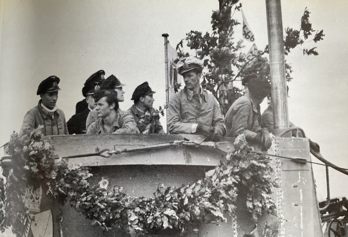
So here is the photo of U203 with the periscope shaft sized antenna mast extending from the bulge:
To assess its size you can compare it to the cylindrical portion of the attack periscope shaft visible above CO Mutzelburg�s left shoulder, behind the garlands.
Assessing the impact of new area rug under modeling table.
I am in the process of building Trumpeter�s 1/48 u-boat. I have a mind to depict the crew replenishing the 8.8cm ready use ammunition. I have photos (on kindle books so I cant post) which show the hatch and chute down which ammo has delivered from the coning tower to the deck. I have one photo showing the ready use ammo locker under the deck where it seems the ready use shells were kept in individual pressure resistant metal containers. What I am struggling with is
Where/how did the ammunition chute go at the top of the coning tower? I have a photo of a crewman crouched down at the front of the coning tower but I cant tell how the shell got from there to the bottom of the chute. Was there a hatch or did they lift up or hinge back a grating?
The ammo store within the boat was, I believe, under the Captains cabin, I have seen a photo which suggested these shells were also stored in individual pressure resistant metal containers, but this doesn�t make sense to me, they were stored within the pressure hull so this seems unnecessary. All the photos of the conning tower ammunition chute in use shows bare shells going down to the deck. It seems to me that it makes sense these shells would be stored in wooden crates for faster handling than in individual sealed containers each of which would need to be opened before the shell could be passed to the deck gun crew. Anyone have definitive info this?
Also any info on the ready use locker in the deck would be helpful, particularly how it was accessed.
Thanks
Fortunately the Bundesarchiv makes available a large number of digitized drawings. One that may help is RM 25/10315, which details the bridge fairwater construction:
The ammunition was sent from the bridge to the deck via two chutes port and starboard to either side of the UZO base.
Jacob
Under Construction:
1/350 Typhoon
1/350 Skate
1/350 USS Nautilus
1/350 Tang
1/350 November
1/350 Hotel II
1/350 Alfa
1/350 George Washington
1/72 Type VIIC
Vepr157 wrote:Fortunately the Bundesarchiv makes available a large number of digitized drawings. One that may help is RM 25/10315, which details the bridge fairwater construction:
Further to Vepr157's last reply and re: ammunition stowages in the Type VII U-boat.
If you now have access to the Invenio search engine and the BaMa has digitised the relevant plan, try searching with the term "Munitions Stauung." There may be more than one plan but one of them should show the stowage arrangements for the 88mm ready use ammunition below the forward casing deck, while another might show the stowage inside the pressure hull.
However, if these have not "survived" there are a number of drawings of the said stowages for WW 1 German U-boats, which should give you a "steer" in the "Folded" collection of German warship plans held by the National Maritime Museum in Greenwich.
That is an interesting project that you have going.
Under Construction:
1/350 Typhoon
1/350 Skate
1/350 USS Nautilus
1/350 Tang
1/350 November
1/350 Hotel II
1/350 Alfa
1/350 George Washington
1/72 Type VIIC