Pomeranian Rahschlup 1846 � 1/160 scale � Baltic trader
Moderators: MartinJQuinn, JIM BAUMANN, HMAS, Tiny69, Dave Wooley
-
wefalck

- Posts: 2079
- Joined: Wed Sep 28, 2011 12:04 pm
- Location: Paris
- Contact:
Re: Pomeranian Rahschlup 1846 � 1/160 scale � Baltic trader
Thanks, Marijn, I am aware of this, but they are like ploughing furrows actually. I only need a very narrow incision to hold some pigmented ink. The lines will be narrower than what can be drawn reasonably with an old-fashioned drafting pen or led alone a marker pen.
Eberhard
Former chairman Arbeitskreis historischer Schiffbau e.V. (German Association for Shipbuilding History)
--------------------------------------------------------------------------------------------------------------------------------------------------------------------------------------------


Former chairman Arbeitskreis historischer Schiffbau e.V. (German Association for Shipbuilding History)
--------------------------------------------------------------------------------------------------------------------------------------------------------------------------------------------
-
wefalck
- Posts: 2079
- Joined: Wed Sep 28, 2011 12:04 pm
- Location: Paris
- Contact:
Re: Pomeranian Rahschlup 1846 � 1/160 scale � Baltic trader
Cabin companionway and binnacle
The layout of the access to the stern cabin is somewhat puzzling, even taking into consideration that accommodation in this kind of vessel was spartanic and cramped. There seems to be a skylight over the cabin that was most probably protected by a grille. However, it is just in the area over which the business end of tiller sweeps. The helmsman would have to pay attention, where he puts his feet. Rather close in front of it seems to be the companionway that leads down into the cabin. Unlike for the other deck openings no coamings are drawn. Normally, there would have been a movable binnacle behind the companionway, so that the helmsman has a good view. The binnacle at that time was constructed like a cabinet and would be lashed down to the deck. However, the space between the skylight and the companionway seems to be too narrow to accommodate this kind of cabinet.
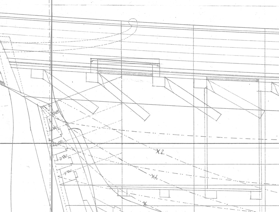
Details of the stern arrangements, original drawing by M�ller (1846)
By looking through contemporary paintings and drawings of similar vessels, I chanced upon a somewhat na�ve watercolour of a local painter from Trondheim, that shows a combination of binnacle and companionway. It also opens in a somewhat unusual fashion, where a segment of the roof is hinged to flip backward � rather than the usual sliding cover. Not sure how this would behave in any kind of stronger wind. Not all the details and the perspective in the watercolour seem to be right, but overall, it looks credible.
The whole arrangement is actually quite similar to that of the original drawing, also with the skylight right under the tiller, which actually is worked quite casually with ropes by the gentleman with straw(?)-hat sitting on the port stern rail.
Anyway, I opted for this solution as it is unusual and solves the space problem. As a bonus I don�t need to worry about rendering the lashings of the binnacle.
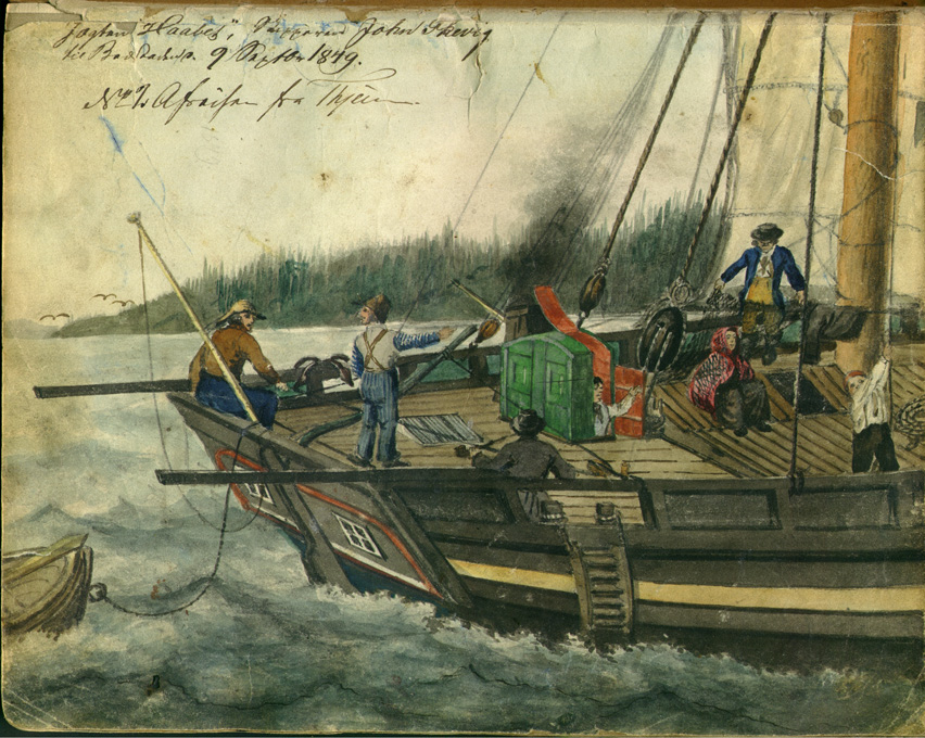
The Norwegian j�gt HAABET (1849). Source: Town archives of Trondheim - https://www.flickr.com/photos/trondheim ... 3539132719.
The companionway-binnacle combination was again built from laminations of laser-cut pieces. The main objective was to show the panelling. So, each side was built up from three layers, the outer ones simulating the frames with the cut-outs for the panels. The profiled coamings were simulated by adding two further layers.
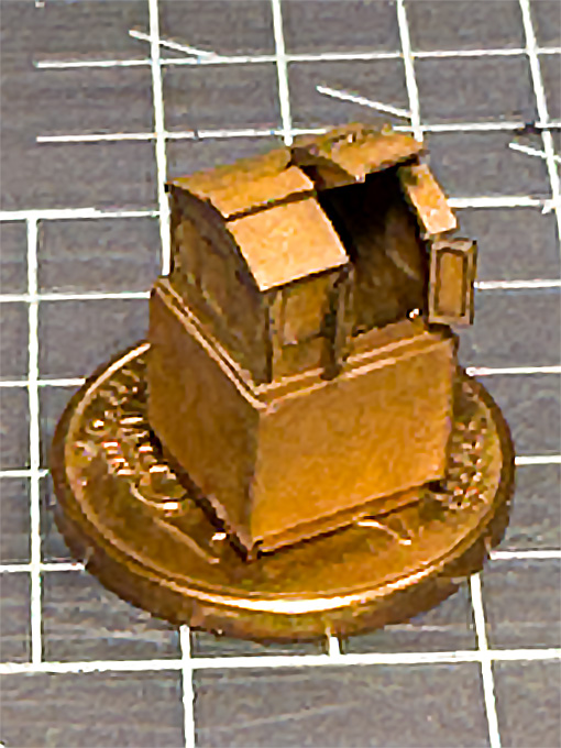


The collection of parts for laser-cutting
Assembly of all those parts was a bit of fiddling and I prefer my usual method of assembling companionways etc. around a solid core milled from a piece of acrylic glass, but this obviously only works, when they are shown closed.
To be continued �
The layout of the access to the stern cabin is somewhat puzzling, even taking into consideration that accommodation in this kind of vessel was spartanic and cramped. There seems to be a skylight over the cabin that was most probably protected by a grille. However, it is just in the area over which the business end of tiller sweeps. The helmsman would have to pay attention, where he puts his feet. Rather close in front of it seems to be the companionway that leads down into the cabin. Unlike for the other deck openings no coamings are drawn. Normally, there would have been a movable binnacle behind the companionway, so that the helmsman has a good view. The binnacle at that time was constructed like a cabinet and would be lashed down to the deck. However, the space between the skylight and the companionway seems to be too narrow to accommodate this kind of cabinet.
Details of the stern arrangements, original drawing by M�ller (1846)
By looking through contemporary paintings and drawings of similar vessels, I chanced upon a somewhat na�ve watercolour of a local painter from Trondheim, that shows a combination of binnacle and companionway. It also opens in a somewhat unusual fashion, where a segment of the roof is hinged to flip backward � rather than the usual sliding cover. Not sure how this would behave in any kind of stronger wind. Not all the details and the perspective in the watercolour seem to be right, but overall, it looks credible.
The whole arrangement is actually quite similar to that of the original drawing, also with the skylight right under the tiller, which actually is worked quite casually with ropes by the gentleman with straw(?)-hat sitting on the port stern rail.
Anyway, I opted for this solution as it is unusual and solves the space problem. As a bonus I don�t need to worry about rendering the lashings of the binnacle.
The Norwegian j�gt HAABET (1849). Source: Town archives of Trondheim - https://www.flickr.com/photos/trondheim ... 3539132719.
The companionway-binnacle combination was again built from laminations of laser-cut pieces. The main objective was to show the panelling. So, each side was built up from three layers, the outer ones simulating the frames with the cut-outs for the panels. The profiled coamings were simulated by adding two further layers.
The collection of parts for laser-cutting
Assembly of all those parts was a bit of fiddling and I prefer my usual method of assembling companionways etc. around a solid core milled from a piece of acrylic glass, but this obviously only works, when they are shown closed.
To be continued �
Eberhard
Former chairman Arbeitskreis historischer Schiffbau e.V. (German Association for Shipbuilding History)
--------------------------------------------------------------------------------------------------------------------------------------------------------------------------------------------
Former chairman Arbeitskreis historischer Schiffbau e.V. (German Association for Shipbuilding History)
--------------------------------------------------------------------------------------------------------------------------------------------------------------------------------------------
-
Michel.fr
- Posts: 8
- Joined: Sun Jun 01, 2025 4:07 am
- Location: France
Re: Pomeranian Rahschlup 1846 � 1/160 scale � Baltic trader
Hello,
I just viewed this post. Wonderful ! An advanced research of documents and an excellent start of work.
Best wishes
I just viewed this post. Wonderful ! An advanced research of documents and an excellent start of work.
Best wishes
-
wefalck
- Posts: 2079
- Joined: Wed Sep 28, 2011 12:04 pm
- Location: Paris
- Contact:
Re: Pomeranian Rahschlup 1846 � 1/160 scale � Baltic trader
Thank you very much for your kind comments!
In between business-related absences from home, I managed to progress here a bit ...
****************
Cabin Skylight
As noted previously, the cabin skylight is a somewhat perilous position, but nevertheless contemporary drawings and some old models indicated, that they were of relatively lightweight construction. The actual construction is somewhat conjectural, but it seems that the hatch was covered by frame into which glass-panes were insert. Over this, there is a shallow roof-like structure with protective iron bars. In this arrangement, the glass-panes are not actually insert into the roof-like structure, but are at some distance below. The effect is, that even in the event that the iron bars are bent, the glass would not be touched. It also conceivable, that in the Baltic not real glass was used, but rather muscovite, which would be obtained by trade from Russia. In the event of very bad weather, the roof-like grille presumably could be replaced by a plain hatch cover.

Milling to shape of the acrylic glass core for the cabin skylight
This structure was built up in my preferred way, that is around a core of acrylic glass. It was milled to size from scrap piece of acrylic glass. For the �glass� surface, I was able to use one of the original - as manufactured - surfaces, so no polishing was required. The high-speed milling with a fly-cutter a low feed-rate left almost transparent surfaces.

Milling to shape of the acrylic glass core for the cabin skylight

Milling of the recesses for the laser-cut frame parts
The parts for the roof-like structure were produced again with the laser-cutter from Canson paper. The structure was to be designed in two parts, namely the frame attached to acrylic core and the two roof halves with the grilles, to allow painting. During painting the horizontal pane will be masked off and the roof halves painted separately.
In order to ensure equal spacing of the �bars�, the roof was built up from three layers with the middle layers having notches. This layer was lacquered onto one of the outer layers and the �bars� attached with drops of varnish � quite a fiddly bit of work and I am not entirely satisfied with the result. In the past, I made such parts from surface-etched brass and this seems to have worked better, but I didn�t want to set up everything for etching just a couple of small parts.

Basic structure of the skylight, waiting to be painted and finally assembled
I prefer to defer painting to the late stages of the building process in order to avoid handling the painted parts as much as possible, so construction of the skylight stops here for the moment.
To be continued �
In between business-related absences from home, I managed to progress here a bit ...
****************
Cabin Skylight
As noted previously, the cabin skylight is a somewhat perilous position, but nevertheless contemporary drawings and some old models indicated, that they were of relatively lightweight construction. The actual construction is somewhat conjectural, but it seems that the hatch was covered by frame into which glass-panes were insert. Over this, there is a shallow roof-like structure with protective iron bars. In this arrangement, the glass-panes are not actually insert into the roof-like structure, but are at some distance below. The effect is, that even in the event that the iron bars are bent, the glass would not be touched. It also conceivable, that in the Baltic not real glass was used, but rather muscovite, which would be obtained by trade from Russia. In the event of very bad weather, the roof-like grille presumably could be replaced by a plain hatch cover.
Milling to shape of the acrylic glass core for the cabin skylight
This structure was built up in my preferred way, that is around a core of acrylic glass. It was milled to size from scrap piece of acrylic glass. For the �glass� surface, I was able to use one of the original - as manufactured - surfaces, so no polishing was required. The high-speed milling with a fly-cutter a low feed-rate left almost transparent surfaces.
Milling to shape of the acrylic glass core for the cabin skylight
Milling of the recesses for the laser-cut frame parts
The parts for the roof-like structure were produced again with the laser-cutter from Canson paper. The structure was to be designed in two parts, namely the frame attached to acrylic core and the two roof halves with the grilles, to allow painting. During painting the horizontal pane will be masked off and the roof halves painted separately.
In order to ensure equal spacing of the �bars�, the roof was built up from three layers with the middle layers having notches. This layer was lacquered onto one of the outer layers and the �bars� attached with drops of varnish � quite a fiddly bit of work and I am not entirely satisfied with the result. In the past, I made such parts from surface-etched brass and this seems to have worked better, but I didn�t want to set up everything for etching just a couple of small parts.
Basic structure of the skylight, waiting to be painted and finally assembled
I prefer to defer painting to the late stages of the building process in order to avoid handling the painted parts as much as possible, so construction of the skylight stops here for the moment.
To be continued �
Eberhard
Former chairman Arbeitskreis historischer Schiffbau e.V. (German Association for Shipbuilding History)
--------------------------------------------------------------------------------------------------------------------------------------------------------------------------------------------
Former chairman Arbeitskreis historischer Schiffbau e.V. (German Association for Shipbuilding History)
--------------------------------------------------------------------------------------------------------------------------------------------------------------------------------------------
-
marijn van gils
- Posts: 2686
- Joined: Tue Feb 06, 2007 10:24 am
- Location: Belgium
Re: Pomeranian Rahschlup 1846 � 1/160 scale � Baltic trader
Beautiful precise scratchbuilding! 
And with very interesting techniques too!
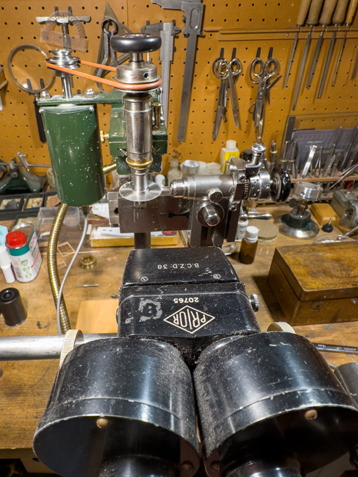
That milling machine looks beautiful. Is it some kind of vintage watchmakers machine?
And with very interesting techniques too!
That milling machine looks beautiful. Is it some kind of vintage watchmakers machine?
-
wefalck
- Posts: 2079
- Joined: Wed Sep 28, 2011 12:04 pm
- Location: Paris
- Contact:
Re: Pomeranian Rahschlup 1846 � 1/160 scale � Baltic trader
Thanks, Marijn!
Well, it's a vintage milling machine that never was:�https://www.maritima-et-mechanika.org/t ... omill.html. The key mechanical parts came from antique watchmaking lathes.

https://www.maritima-et-mechanika.org/t ... /MF-V1.mp4
The miniature vice is shop-made:�https://www.maritima-et-mechanika.org/t ... Micro_vice
Well, it's a vintage milling machine that never was:�https://www.maritima-et-mechanika.org/t ... omill.html. The key mechanical parts came from antique watchmaking lathes.
https://www.maritima-et-mechanika.org/t ... /MF-V1.mp4
The miniature vice is shop-made:�https://www.maritima-et-mechanika.org/t ... Micro_vice
Eberhard
Former chairman Arbeitskreis historischer Schiffbau e.V. (German Association for Shipbuilding History)
--------------------------------------------------------------------------------------------------------------------------------------------------------------------------------------------
Former chairman Arbeitskreis historischer Schiffbau e.V. (German Association for Shipbuilding History)
--------------------------------------------------------------------------------------------------------------------------------------------------------------------------------------------
-
marijn van gils
- Posts: 2686
- Joined: Tue Feb 06, 2007 10:24 am
- Location: Belgium
Re: Pomeranian Rahschlup 1846 � 1/160 scale � Baltic trader
Wow, that really is another hobby in its own right! Fantastic! 
-
wefalck
- Posts: 2079
- Joined: Wed Sep 28, 2011 12:04 pm
- Location: Paris
- Contact:
Re: Pomeranian Rahschlup 1846 � 1/160 scale � Baltic trader
In spite of a week's absence due to some business travel I managed to do something:
*******************
The Main Hatch
The main hatch will be shown closed, so I could revert to my usual technique of milling it from a solid piece of acrylic glass. In fact, the piece forms a core and as sharp corners for the recess into which the hatch covers fit is needed, around it strips of 1 mm acrylic glass were cemented. This arrangement was milled to size and shape as shown previously. To make it visually more interesting a quarter-round cove was milled into the outer edge with a 0.5 mm ball-burr. In real life, this would also prevent the wood from splintering, when hit by something during loading.

Milling a quarter-round cove into the coaming of the main-hatch
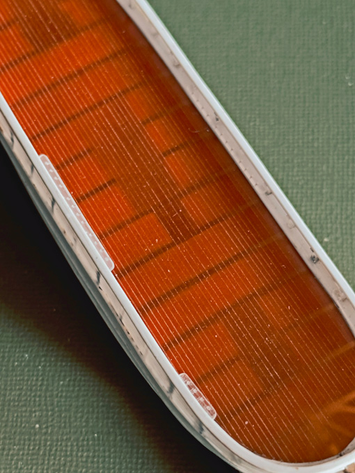
The cover was assumed to be in three parts, each planked with short lengths of plank. The cover is made from a tight-fitting piece of bakelite paper into which the planks were engraved, as was done for the deck-planks. Making hatch and cover in separate pieces allows to paint it with sharp edges. The cover will be simulated to be natural wood.
The main-hatch with the cover inserted
Eventually, the hatch will be fitted with clamps for the battens to tie-down the canvas cover. That will be done at a later stage to avoid damage during fitting the part into the deck.
To be continued �
*******************
The Main Hatch
The main hatch will be shown closed, so I could revert to my usual technique of milling it from a solid piece of acrylic glass. In fact, the piece forms a core and as sharp corners for the recess into which the hatch covers fit is needed, around it strips of 1 mm acrylic glass were cemented. This arrangement was milled to size and shape as shown previously. To make it visually more interesting a quarter-round cove was milled into the outer edge with a 0.5 mm ball-burr. In real life, this would also prevent the wood from splintering, when hit by something during loading.
Milling a quarter-round cove into the coaming of the main-hatch
The cover was assumed to be in three parts, each planked with short lengths of plank. The cover is made from a tight-fitting piece of bakelite paper into which the planks were engraved, as was done for the deck-planks. Making hatch and cover in separate pieces allows to paint it with sharp edges. The cover will be simulated to be natural wood.
The main-hatch with the cover inserted
Eventually, the hatch will be fitted with clamps for the battens to tie-down the canvas cover. That will be done at a later stage to avoid damage during fitting the part into the deck.
To be continued �
Eberhard
Former chairman Arbeitskreis historischer Schiffbau e.V. (German Association for Shipbuilding History)
--------------------------------------------------------------------------------------------------------------------------------------------------------------------------------------------
Former chairman Arbeitskreis historischer Schiffbau e.V. (German Association for Shipbuilding History)
--------------------------------------------------------------------------------------------------------------------------------------------------------------------------------------------
-
wefalck
- Posts: 2079
- Joined: Wed Sep 28, 2011 12:04 pm
- Location: Paris
- Contact:
Re: Pomeranian Rahschlup 1846 � 1/160 scale � Baltic trader
I managed to eek out a bit of time for the workshop between travels and addressed myself to the
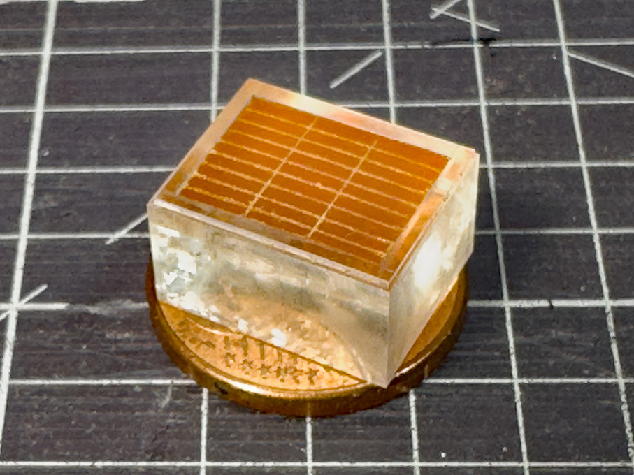
Parcel Hatch
The �parcel hatch� is a common feature of such trading-smack type vessels and proved access to the cargo hold before the mast. As the name indicates, this space was typically used to store general cargo, while the main hold was used for bulk loads, such as bricks or coal, or grain in sacks.
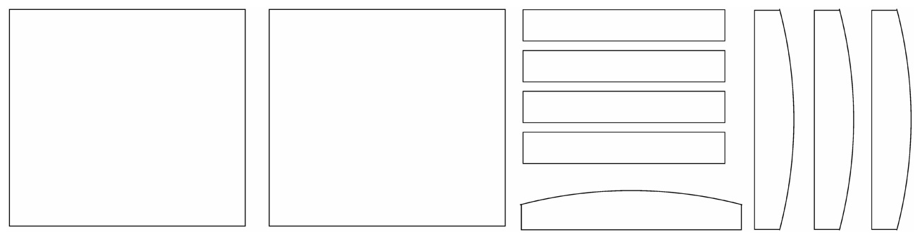
The laser-cutting template for the parcel hatch lid
This hatch will be shown closed and therefore a �core� (the actual hatch including the coamings) was milled from a piece of acrylic, while the lid was built up from laser-cut parts. I could have milled the two parts in one piece, but milling the camber of the lid would have required a more complex set-up. On the real thing lid was made to fit over hatch like the lid on a box.
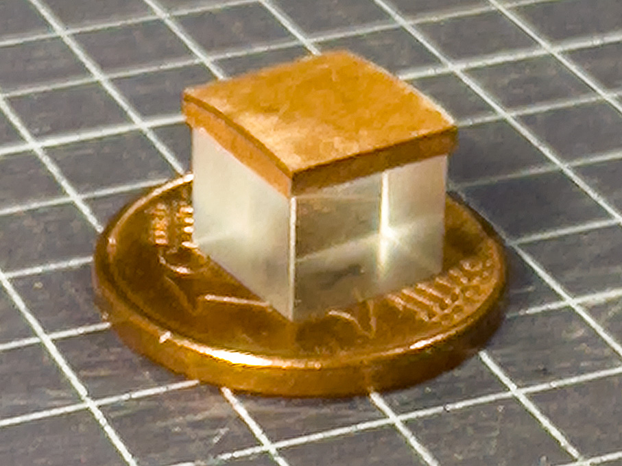
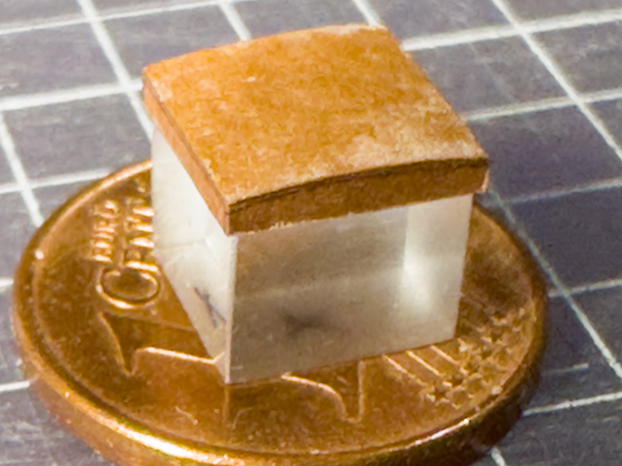
These hatch lid was tied down with two iron straps, the ends of which slipped over eye-bolts in the deck, to be secured to them with cotter-pins presumably. As these parts will be painted in a different colour from that of the hatch and have to fit tightly, they will be made and fitted later, once the hatch is installed.
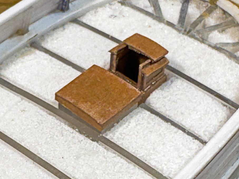
The parcel hatch and crew companionway provisionally deployed
To be continued �
Parcel Hatch
The �parcel hatch� is a common feature of such trading-smack type vessels and proved access to the cargo hold before the mast. As the name indicates, this space was typically used to store general cargo, while the main hold was used for bulk loads, such as bricks or coal, or grain in sacks.
The laser-cutting template for the parcel hatch lid
This hatch will be shown closed and therefore a �core� (the actual hatch including the coamings) was milled from a piece of acrylic, while the lid was built up from laser-cut parts. I could have milled the two parts in one piece, but milling the camber of the lid would have required a more complex set-up. On the real thing lid was made to fit over hatch like the lid on a box.
These hatch lid was tied down with two iron straps, the ends of which slipped over eye-bolts in the deck, to be secured to them with cotter-pins presumably. As these parts will be painted in a different colour from that of the hatch and have to fit tightly, they will be made and fitted later, once the hatch is installed.
The parcel hatch and crew companionway provisionally deployed
To be continued �
Eberhard
Former chairman Arbeitskreis historischer Schiffbau e.V. (German Association for Shipbuilding History)
--------------------------------------------------------------------------------------------------------------------------------------------------------------------------------------------
Former chairman Arbeitskreis historischer Schiffbau e.V. (German Association for Shipbuilding History)
--------------------------------------------------------------------------------------------------------------------------------------------------------------------------------------------
-
wefalck
- Posts: 2079
- Joined: Wed Sep 28, 2011 12:04 pm
- Location: Paris
- Contact:
Re: Pomeranian Rahschlup 1846 � 1/160 scale � Baltic trader
Back from another travel, I turned my attention to the
Anchor-winch 1
I spent quite a bit of time perusing contemporary drawings and near-contemporary models of small mid-19th century Baltic vessels in order to get a good idea of what, at that time, the anchor-winch of a modest small vessel might have looked like. While the archives of the Danish Royal Shipyard in Copenhagen indicate, that winches with mechanical advantage, such as those driven via gears and an idler-shaft or patent-winches seem to have been known by the mid-1830s, they don�t seem to have been common on more modest vessels. Vessels, such as this Rahschlup, were built in small shipyards with limited forging and other iron-working capabilities, let alone gear-cutting facilities. Gears could have been bought in, but this would have been too expensive probably for this kind of �subsistence� shipping.
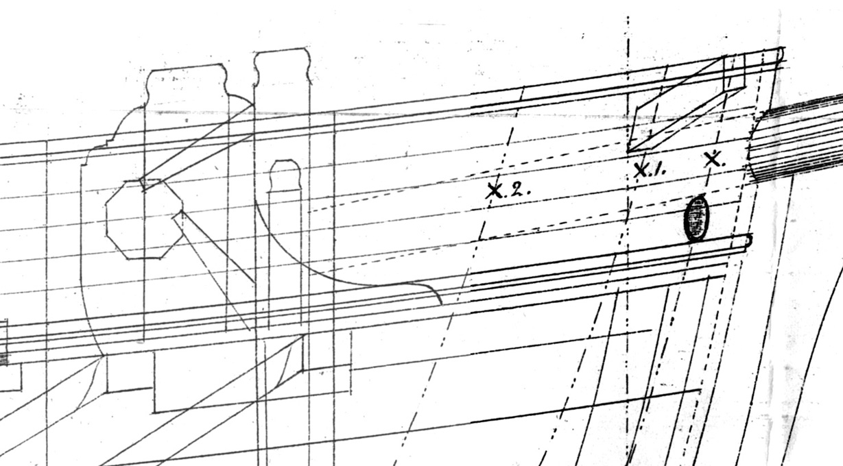
Profile of the winch � Detail from the Original drawing for the Rahschlup.
This research was needed, because the original drawings show the profile of the cheeks, but there is no plan view, that indicates the length and shape of the barrel. In the Danish archive I found the drawing of a single-masted jagt of comparable size with relatively detailed rendering of the winch. It may be a bit older than the Rahschlup, but the original drawings indicate an eight-sided barrel, which at that time was already a bit old-fashioned. Other drawings from the Danish archive of the mid-1840s showed already more modern looking round barrels.
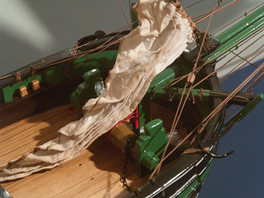
Jacht THETIS (1842) � Late 19th model from original drawings in the Altonaer Museum, Hamburg.
The Danish drawings and various photographs from similar vessels under restauration confirmed that the cheeks were surprisingly thin, only about half a foot in thickness. Similarly, the post against which the bowsprit will rest was only � of a foot in cross-section.
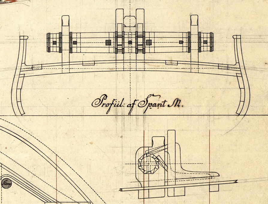
Detail from a drawing F150-119 for a Jagt, Rigsarkivet Copenhagen.
Based on this information, I drew the barrel and the cheeks as working drawings. The drawings for the cheeks will be printed and stuck onto 1 mm acrylic glass as a guidance for sawing them out.
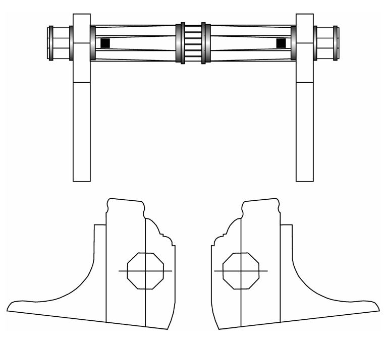
Working drawing for the anchor-winch of the Rahschlup
Workshop results coming hopefully soon �
Anchor-winch 1
I spent quite a bit of time perusing contemporary drawings and near-contemporary models of small mid-19th century Baltic vessels in order to get a good idea of what, at that time, the anchor-winch of a modest small vessel might have looked like. While the archives of the Danish Royal Shipyard in Copenhagen indicate, that winches with mechanical advantage, such as those driven via gears and an idler-shaft or patent-winches seem to have been known by the mid-1830s, they don�t seem to have been common on more modest vessels. Vessels, such as this Rahschlup, were built in small shipyards with limited forging and other iron-working capabilities, let alone gear-cutting facilities. Gears could have been bought in, but this would have been too expensive probably for this kind of �subsistence� shipping.
Profile of the winch � Detail from the Original drawing for the Rahschlup.
This research was needed, because the original drawings show the profile of the cheeks, but there is no plan view, that indicates the length and shape of the barrel. In the Danish archive I found the drawing of a single-masted jagt of comparable size with relatively detailed rendering of the winch. It may be a bit older than the Rahschlup, but the original drawings indicate an eight-sided barrel, which at that time was already a bit old-fashioned. Other drawings from the Danish archive of the mid-1840s showed already more modern looking round barrels.
Jacht THETIS (1842) � Late 19th model from original drawings in the Altonaer Museum, Hamburg.
The Danish drawings and various photographs from similar vessels under restauration confirmed that the cheeks were surprisingly thin, only about half a foot in thickness. Similarly, the post against which the bowsprit will rest was only � of a foot in cross-section.
Detail from a drawing F150-119 for a Jagt, Rigsarkivet Copenhagen.
Based on this information, I drew the barrel and the cheeks as working drawings. The drawings for the cheeks will be printed and stuck onto 1 mm acrylic glass as a guidance for sawing them out.
Working drawing for the anchor-winch of the Rahschlup
Workshop results coming hopefully soon �
Eberhard
Former chairman Arbeitskreis historischer Schiffbau e.V. (German Association for Shipbuilding History)
--------------------------------------------------------------------------------------------------------------------------------------------------------------------------------------------
Former chairman Arbeitskreis historischer Schiffbau e.V. (German Association for Shipbuilding History)
--------------------------------------------------------------------------------------------------------------------------------------------------------------------------------------------
-
Iceman 29

- Posts: 1945
- Joined: Tue Sep 29, 2020 4:35 pm
- Location: Bretagne, France
Re: Pomeranian Rahschlup 1846 � 1/160 scale � Baltic trader
Very nice project Eberhard!
Pascal
�Battleship Bretagne 3D: https://vu.fr/FvCY
�SS Delphine 3D: https://vu.fr/NeuO
�SS Nomadic 3D: https://vu.fr/tAyL
�USS Nokomis 3D: https://vu.fr/kntC
�USS Pamanset 3D: https://vu.fr/jXGQ
�Battleship Bretagne 3D: https://vu.fr/FvCY
�SS Delphine 3D: https://vu.fr/NeuO
�SS Nomadic 3D: https://vu.fr/tAyL
�USS Nokomis 3D: https://vu.fr/kntC
�USS Pamanset 3D: https://vu.fr/jXGQ
-
wefalck
- Posts: 2079
- Joined: Wed Sep 28, 2011 12:04 pm
- Location: Paris
- Contact:
Re: Pomeranian Rahschlup 1846 � 1/160 scale � Baltic trader
Thank you very much the encouraging comment ! However ... it becomes very tough to compete against 3d-printed models 
**************************************************
Anchor-winch 2
As planned, the drawings for the cheeks were printed to the correct size and stuck to a piece of 1 mm acrylic glass. A straight edge of the piece was used as reference surface.
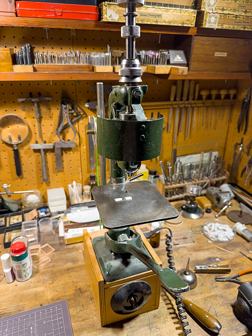
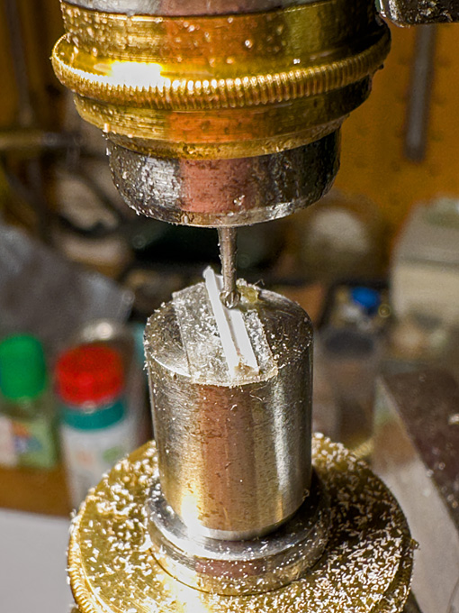
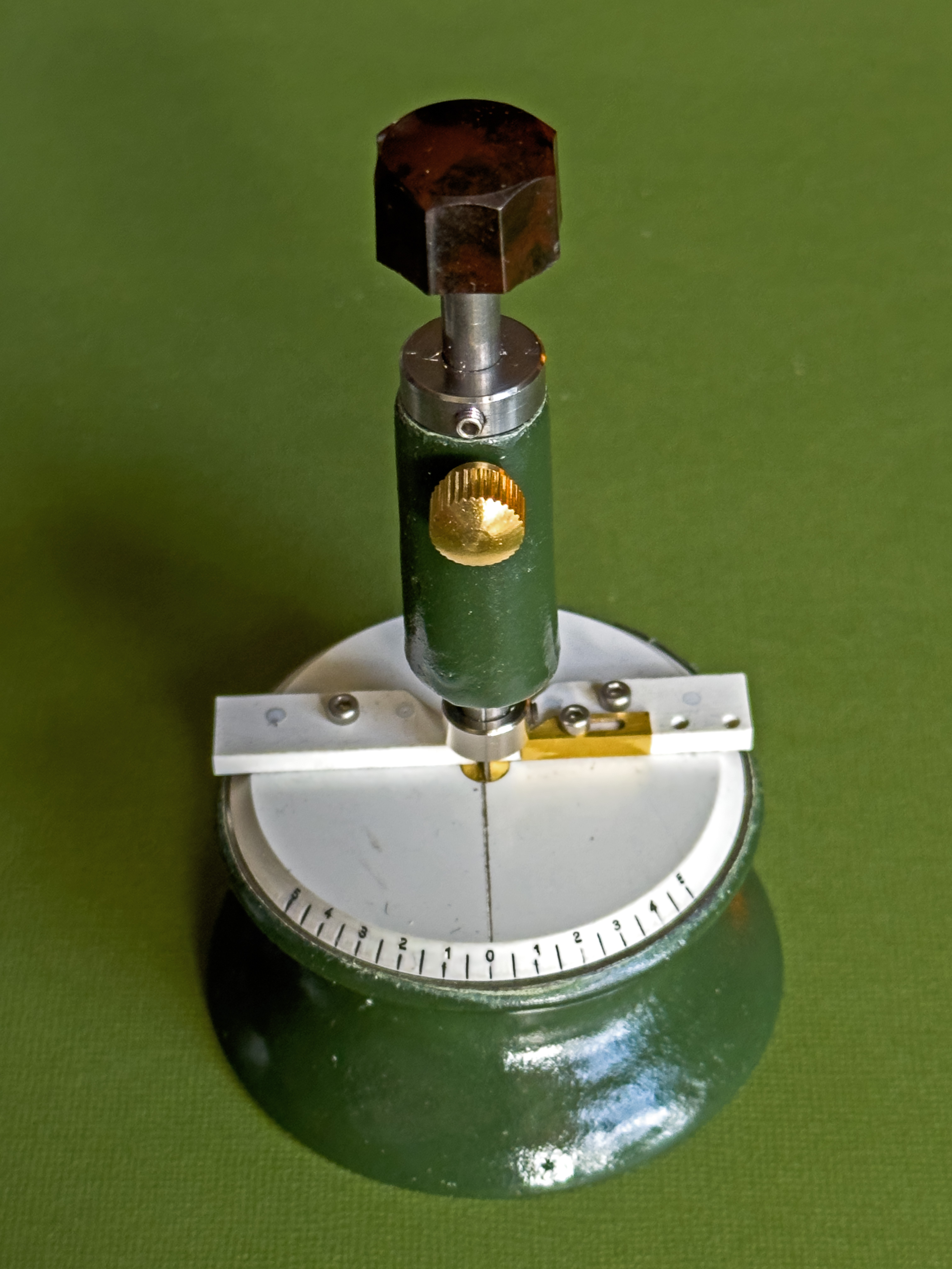
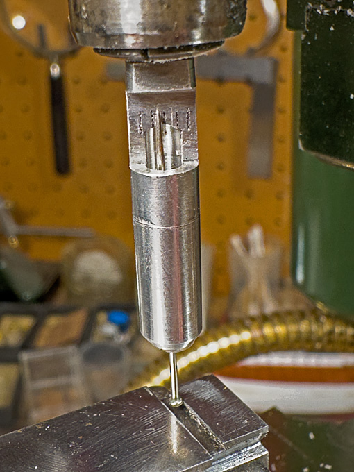
The first step was to drill the 0.5 mm hole for the axle of the winch-drum. This hole serves, together with the straight edge as reference for aligning the two cheeks so that they can be made identical. The drilling gives me the opportunity to show the watchmaker�s pillar drill (https://www.maritima-et-mechanika.org/t ... rills.html) in action.
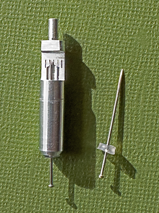
Using the micro-mill as a router, the parts were roughened out with the aid of a fine cylindrical burr. Then a process of hand-filing began, using a variety of small and fine watchmaker�s files.
The edges were slightly rounded using a three-sides scraper and a fine abrasive stick in the handheld electrical drill. Finally the parts were polished with a rotary bristle-brush.
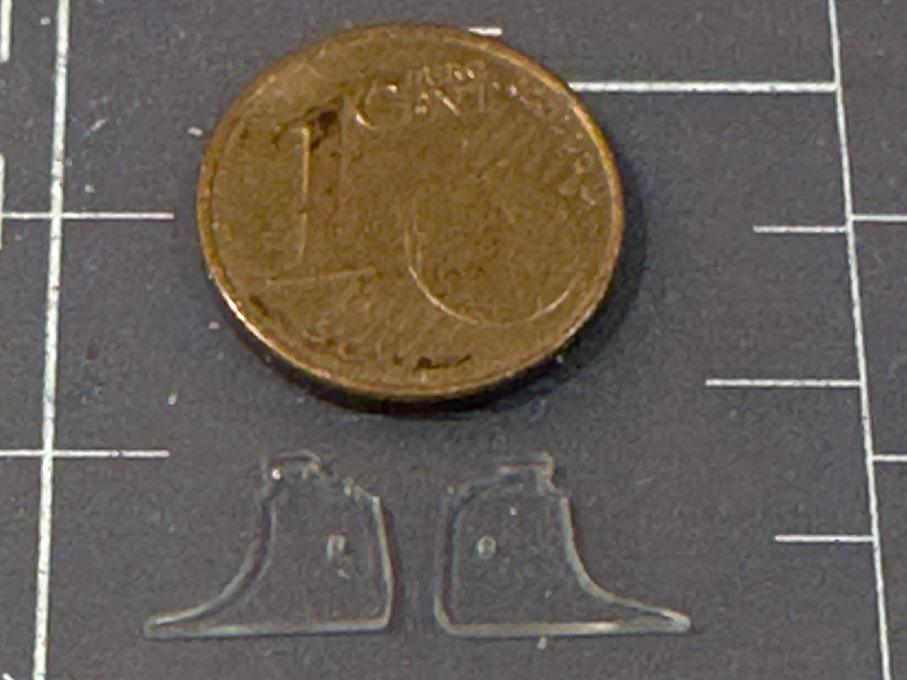
The lower edge of the cheeks is 9 mm long. Unfortunately, the transparent parts are difficult to photograph.
To be continued �
**************************************************
Anchor-winch 2
As planned, the drawings for the cheeks were printed to the correct size and stuck to a piece of 1 mm acrylic glass. A straight edge of the piece was used as reference surface.
The first step was to drill the 0.5 mm hole for the axle of the winch-drum. This hole serves, together with the straight edge as reference for aligning the two cheeks so that they can be made identical. The drilling gives me the opportunity to show the watchmaker�s pillar drill (https://www.maritima-et-mechanika.org/t ... rills.html) in action.
Using the micro-mill as a router, the parts were roughened out with the aid of a fine cylindrical burr. Then a process of hand-filing began, using a variety of small and fine watchmaker�s files.
The edges were slightly rounded using a three-sides scraper and a fine abrasive stick in the handheld electrical drill. Finally the parts were polished with a rotary bristle-brush.
The lower edge of the cheeks is 9 mm long. Unfortunately, the transparent parts are difficult to photograph.
To be continued �
Eberhard
Former chairman Arbeitskreis historischer Schiffbau e.V. (German Association for Shipbuilding History)
--------------------------------------------------------------------------------------------------------------------------------------------------------------------------------------------
Former chairman Arbeitskreis historischer Schiffbau e.V. (German Association for Shipbuilding History)
--------------------------------------------------------------------------------------------------------------------------------------------------------------------------------------------
-
wefalck
- Posts: 2079
- Joined: Wed Sep 28, 2011 12:04 pm
- Location: Paris
- Contact:
Re: Pomeranian Rahschlup 1846 � 1/160 scale � Baltic trader
Anchor-winch 3
The winch drums were fashioned from 3 mm � round acrylic rod. Each side was built up from two pieces. The problem here were the square holes for the handle-bars. In principle, one could cross-drill two holes and file the square, but at 0.5 mm x 0.5 mm this would have been quite a challenge. There would be other options, such as broaching, but this requires specialised tools.
The simplest thing is to divide the drum into two parts, to slot the end of one part, cement the two parts together and one ends up with perfect square holes.
Set up for slotting the ends of the winch drums
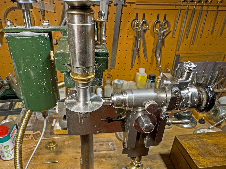
Slotting the winch drums
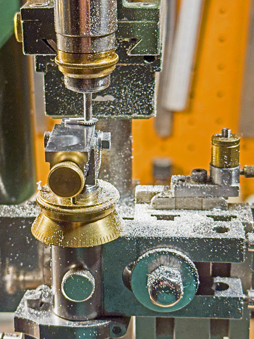
To this end, a piece of rod was faced on both ends, and drilled 0.5 mm for the axle. It was then transferred to the dividing head on the micro-milling machine and the ends were slotted 0.5 mm deep with a 0.5 mm circular saw. Finally, a round disc of the same diameter was cemented to the end, leaving two perfectly square cross-holes.
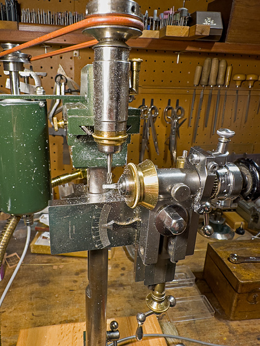
Milling the eight sides of the winch drums
In the next step, the axle of the dividing head was tilted by 1.5� for milling the eight sides of the drum that is slightly conical. The drum is bound by iron hoops at both ends. These were generated by milling the drum to 0.2 mm diameter above the target dimensions. Then, the diameter was reduced by these 0.2 mm, leaving two �bands� of 0.3 mm width and 0.1 mm thickness at both ends.
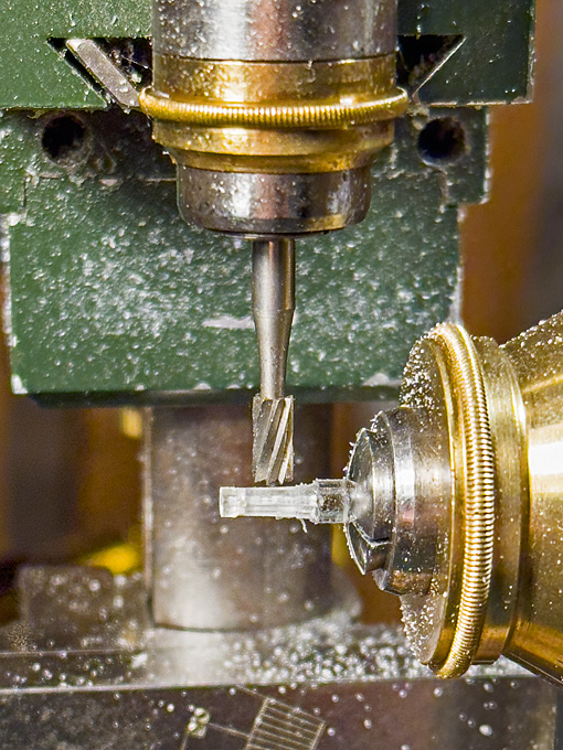
Close-up view of milling the eight sides of the winch drums
The thinner ends of the drum were faced off on the lathe to the correct length and then the drum halves parted off to the correct length.
The spill-heads were done in the same way, but are cylindrical (or eight-sided prisms), rather than conical (or eight-sided truncated pyramids). A smaller burr had to be used, as the distance between the reinforcement bands is only 1 mm. Before parting-off, the outside ends were slightly dished with a round-burr in the lathe tailstock.
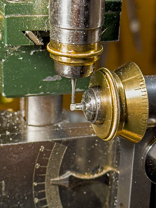
Milling the spill heads
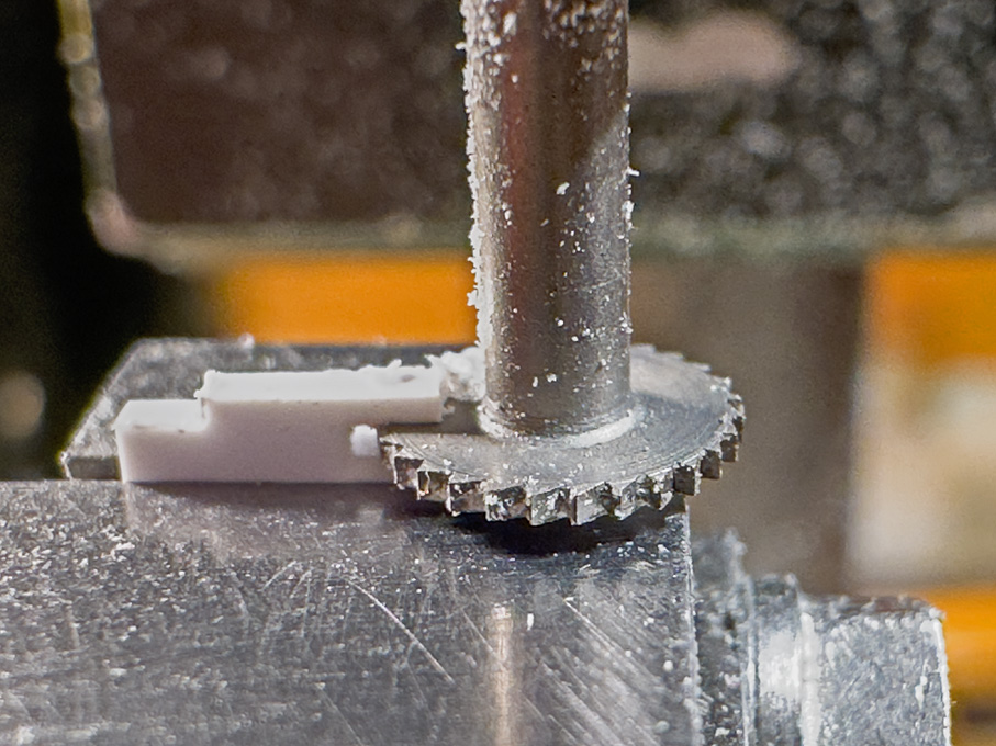
For the ratchet wheel a short length of 3 mm acrylic rod was turned down to 0.1 mm above the target diameter of 2.0 mm. The geometry for milling the ratchets was worked out on the computer. I arrived at ten ratchets 0.2 mm deep (= 32 mm on the prototype, which appears reasonable). In watchmaking there are special ratchet-wheel milling cutters that can also cut curved teeth, but I don�t have any, so I had to make do with a dovetail burr, which is good enough, as the ratchet wheel does not need to be functional. Also, two 0,2 mm thick discs as flanged were parted off.
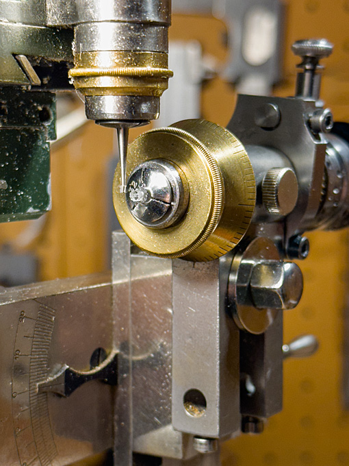
Milling the ratchet wheel
Unfortunately, these transparent parts are difficult to photograph and, indeed difficult to see during machining. A first coat of paint will eventually show any errors �
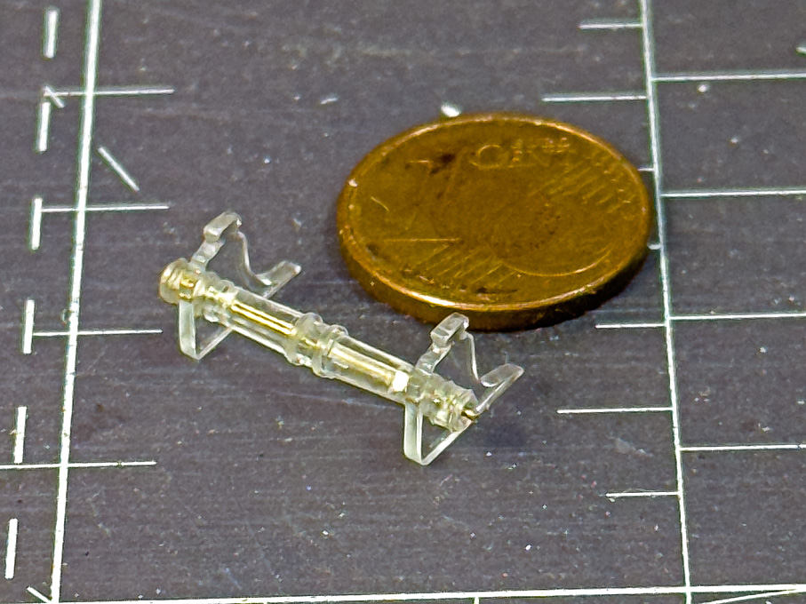
The part of the anchor winch made so far assembled
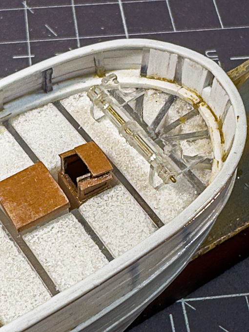
The anchor winch at its future location
To be continued �
The winch drums were fashioned from 3 mm � round acrylic rod. Each side was built up from two pieces. The problem here were the square holes for the handle-bars. In principle, one could cross-drill two holes and file the square, but at 0.5 mm x 0.5 mm this would have been quite a challenge. There would be other options, such as broaching, but this requires specialised tools.
The simplest thing is to divide the drum into two parts, to slot the end of one part, cement the two parts together and one ends up with perfect square holes.
Set up for slotting the ends of the winch drums
Slotting the winch drums
To this end, a piece of rod was faced on both ends, and drilled 0.5 mm for the axle. It was then transferred to the dividing head on the micro-milling machine and the ends were slotted 0.5 mm deep with a 0.5 mm circular saw. Finally, a round disc of the same diameter was cemented to the end, leaving two perfectly square cross-holes.
Milling the eight sides of the winch drums
In the next step, the axle of the dividing head was tilted by 1.5� for milling the eight sides of the drum that is slightly conical. The drum is bound by iron hoops at both ends. These were generated by milling the drum to 0.2 mm diameter above the target dimensions. Then, the diameter was reduced by these 0.2 mm, leaving two �bands� of 0.3 mm width and 0.1 mm thickness at both ends.
Close-up view of milling the eight sides of the winch drums
The thinner ends of the drum were faced off on the lathe to the correct length and then the drum halves parted off to the correct length.
The spill-heads were done in the same way, but are cylindrical (or eight-sided prisms), rather than conical (or eight-sided truncated pyramids). A smaller burr had to be used, as the distance between the reinforcement bands is only 1 mm. Before parting-off, the outside ends were slightly dished with a round-burr in the lathe tailstock.
Milling the spill heads
For the ratchet wheel a short length of 3 mm acrylic rod was turned down to 0.1 mm above the target diameter of 2.0 mm. The geometry for milling the ratchets was worked out on the computer. I arrived at ten ratchets 0.2 mm deep (= 32 mm on the prototype, which appears reasonable). In watchmaking there are special ratchet-wheel milling cutters that can also cut curved teeth, but I don�t have any, so I had to make do with a dovetail burr, which is good enough, as the ratchet wheel does not need to be functional. Also, two 0,2 mm thick discs as flanged were parted off.
Milling the ratchet wheel
Unfortunately, these transparent parts are difficult to photograph and, indeed difficult to see during machining. A first coat of paint will eventually show any errors �
The part of the anchor winch made so far assembled
The anchor winch at its future location
To be continued �
Eberhard
Former chairman Arbeitskreis historischer Schiffbau e.V. (German Association for Shipbuilding History)
--------------------------------------------------------------------------------------------------------------------------------------------------------------------------------------------
Former chairman Arbeitskreis historischer Schiffbau e.V. (German Association for Shipbuilding History)
--------------------------------------------------------------------------------------------------------------------------------------------------------------------------------------------
-
marijn van gils
- Posts: 2686
- Joined: Tue Feb 06, 2007 10:24 am
- Location: Belgium
Re: Pomeranian Rahschlup 1846 � 1/160 scale � Baltic trader
Now that's precision-manufacturing!
I also look forward to seeing a coat of paint on it. That will bring out the sharpness of the detail.
I also look forward to seeing a coat of paint on it. That will bring out the sharpness of the detail.
-
wefalck
- Posts: 2079
- Joined: Wed Sep 28, 2011 12:04 pm
- Location: Paris
- Contact:
Re: Pomeranian Rahschlup 1846 � 1/160 scale � Baltic trader
The shipyard had been closed for much of August, only the drawing office stayed open to prepare work for autumn ...
********************
Anchor-winch 4
The remaining item for the winch is the pawl-bit against which also the bowsprit rests. It is surprisingly thin, only 240 mm square, according to the original drawing, which conveniently translates to 1.5 mm on the model.
A strip a tad wider than 2 mm was cut from a scrap of 1.5 mm thick acrylic glass. Care was taken to cut it parallel to a manufacturing edge, which is clean and square. In this way, only one edge needed to be machined and the manufactured edge provided a good datum for this.
The pawl rest in a cast-iron U-shaped frame that is bolted to the front of the post (updating the design a bit from the older style wooden pawls drawn in the original drawing). Rather than adding this part to the post, I decided to mill it from the solid. Hence the 2 mm strip.
Originally, I intended to drill 0.15 mm holes for the axes of the pawls, but my drills turned out to be too short for that. This would not be really necessary at this scale anyway, but would have later, once a wire was inserted, facilitated the positioning of the pawls. I have to eyeball it now.

Milling the groove into the �cast-iron� frame
The post was milled to size, letting material for the frame for the pawls standing. The shape of the frame was then milled out and the ends rounded with a safe-edge file. In the final machining step, the groove was cut.

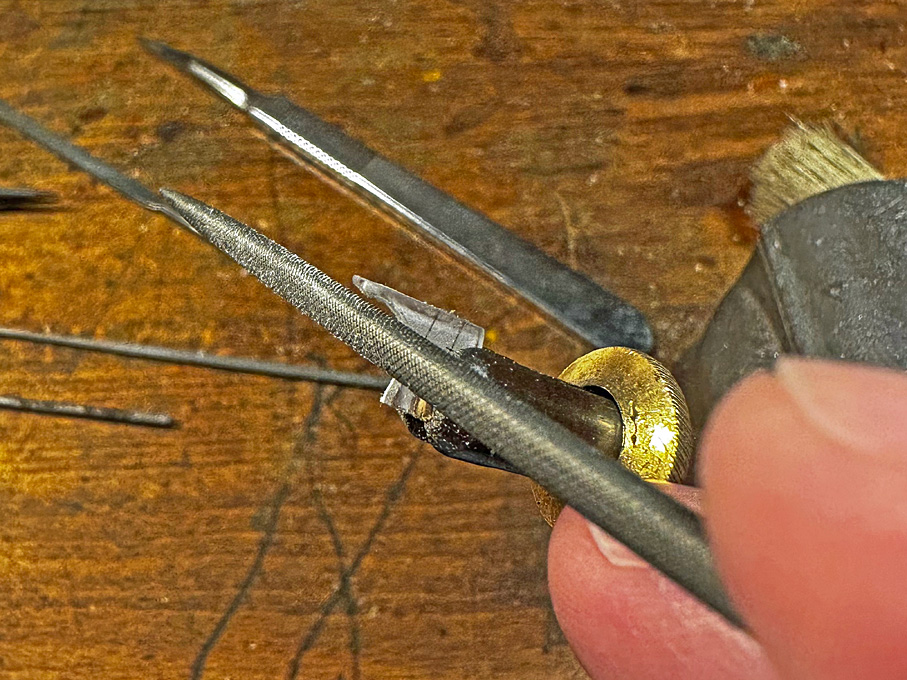
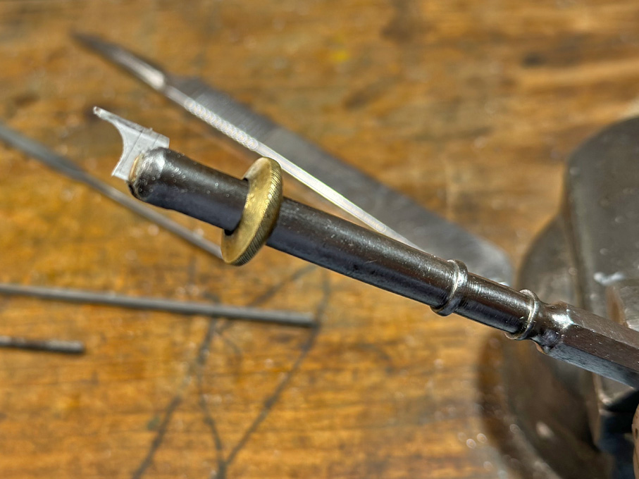
Shaping the head of the pawl-bit
I don�t have square collets (I plan to make one day a set of square insert collets for precisely holding square stock), so a round one had to make do for the next operation, namely shaping the head of the pawl-bit with different burrs. Because of the relatively soft acrylic glass and with light cuts, this is not a problem.

Shaping the head of the pawl-bit
The pawls will be short lengths of 0.2 mm x 1 mm styrene strips, but will be made only later, when everything comes together so as not to lose those tiny bits.
To be continued �
********************
Anchor-winch 4
The remaining item for the winch is the pawl-bit against which also the bowsprit rests. It is surprisingly thin, only 240 mm square, according to the original drawing, which conveniently translates to 1.5 mm on the model.
A strip a tad wider than 2 mm was cut from a scrap of 1.5 mm thick acrylic glass. Care was taken to cut it parallel to a manufacturing edge, which is clean and square. In this way, only one edge needed to be machined and the manufactured edge provided a good datum for this.
The pawl rest in a cast-iron U-shaped frame that is bolted to the front of the post (updating the design a bit from the older style wooden pawls drawn in the original drawing). Rather than adding this part to the post, I decided to mill it from the solid. Hence the 2 mm strip.
Originally, I intended to drill 0.15 mm holes for the axes of the pawls, but my drills turned out to be too short for that. This would not be really necessary at this scale anyway, but would have later, once a wire was inserted, facilitated the positioning of the pawls. I have to eyeball it now.
Milling the groove into the �cast-iron� frame
The post was milled to size, letting material for the frame for the pawls standing. The shape of the frame was then milled out and the ends rounded with a safe-edge file. In the final machining step, the groove was cut.
Shaping the head of the pawl-bit
I don�t have square collets (I plan to make one day a set of square insert collets for precisely holding square stock), so a round one had to make do for the next operation, namely shaping the head of the pawl-bit with different burrs. Because of the relatively soft acrylic glass and with light cuts, this is not a problem.
Shaping the head of the pawl-bit
The pawls will be short lengths of 0.2 mm x 1 mm styrene strips, but will be made only later, when everything comes together so as not to lose those tiny bits.
To be continued �
Eberhard
Former chairman Arbeitskreis historischer Schiffbau e.V. (German Association for Shipbuilding History)
--------------------------------------------------------------------------------------------------------------------------------------------------------------------------------------------
Former chairman Arbeitskreis historischer Schiffbau e.V. (German Association for Shipbuilding History)
--------------------------------------------------------------------------------------------------------------------------------------------------------------------------------------------
-
wefalck
- Posts: 2079
- Joined: Wed Sep 28, 2011 12:04 pm
- Location: Paris
- Contact:
Re: Pomeranian Rahschlup 1846 � 1/160 scale � Baltic trader
Thank you very much for the continued interest as evidenced by the number of 'klicks' on the building log
**********************
Developing the Rigging Warrant
It may seem strange to talk about the rigging warrant at this stage, but as much of the supporting fittings have to be reconstructed from sources and certain fittings, such as pin-rails or cleats, have to be put into place before painting, now is the time to develop at least an outline for it.

Spar-dimensions as per table on original drawing by M�ller
The original drawings comprise a sail-plan and a spar-list with dimensions, which is a good start. However, as this is the builder�s and not a modeller�s plan, there are no details on the actual execution of the rig. These have to be reconstructed from sources from around the middle of the 19th century, notably
BIDDLECOMBE, G. (1848): The Art of Rigging.- 155 p., Salem, Ma. (Reprint 1990 by Dover Publication, New York).
BOBRIK, E. (1848): Handbuch der praktischen Seefahrtskunde, Schiffgeb�udekunde, Zur�stungskunde, Man�vrierkunde, Ankerkunde, Tafeln zur Schifferkunde.- 604 p. + plates, Leipzig (reprint 1978 by Horst Hamecher, Kassel).
COST�, F.-A. (18292): Manuel de Gr�ement ou l�art d��quiper les vaisseaux et autres batimens de mer, de tout ce qui est n�cessaire a leurs mouvements.- 282 p., tables, Paris (Dezauche).
JA�, . (1860): �tudes sur le Gre�ment d�apr�s les r�glement du 25 avril 1857, r�vis� en 1858.- Atlas du G�nie Maritime, 2�me Serie, Annexe No. 1: 55 pl., Paris (Minist�re de la Marine et des Colonies).
KIPPING, R. (1853): Rudimentary Treatise on Masting, Mast-Making, and Rigging of Ships.- 150 p., London (John Weale).
MIDDENDORF, F.L. (1903): Bemastung und Takelung der Schiffe.- 401 p., Kassel (reprint 1977 by Horst Hamecher). � this is a bit late, but has useful tables with dimensions of parts
While these works contain many useful tables and sometimes beautiful detailed drawings, I realised that they are of limited use for this project as they mainly deal with larger ships. Only occasionally they give information on rigging practice for single-masted vessels. In some cases information on the foremast and bowsprit/jibboom of topsail-schooner was useful, as their rigging layout is similar.
The popular secondary literature on, e.g. British or French naval cutters, that have at a first glance a similar sail-plan, also is only of limited value, as they typically have a running bowsprit, and not a fixed one with jib-boom.
So, much had to be interpolated, also from secondary sources covering earlier or later periods.
I also studied numerous images of German, Danish, Swedish, and Norwegian sloops operating in the Baltic with respect to the arrangement of stays, shrouds, backstays, topmast-shrouds, -stays, -backstays, and the bowsprit/jibboom. A considerable variability in layouts was observed.
Although the models of sloops and topsail-schooners in the Altona Museum (Hamburg) were built and rigged at the turn of the 19th to the 20th century, the model builders included older professional riggers, who presumably were aware of the earlier practices. These models give a good overview of the variability of rigging layouts and the supporting structures at the hull and on the deck.
With this information it has been possible to develop a draft warrant for the standing and (part of) the running that will help to dimension and locate the necessary pin-rails, rigging cleats, bollards, etc.

Reconstructed dimensions for the standing rigging

Reconstructed dimensions for (part of) the running rigging
To be continued �
**********************
Developing the Rigging Warrant
It may seem strange to talk about the rigging warrant at this stage, but as much of the supporting fittings have to be reconstructed from sources and certain fittings, such as pin-rails or cleats, have to be put into place before painting, now is the time to develop at least an outline for it.
Spar-dimensions as per table on original drawing by M�ller
The original drawings comprise a sail-plan and a spar-list with dimensions, which is a good start. However, as this is the builder�s and not a modeller�s plan, there are no details on the actual execution of the rig. These have to be reconstructed from sources from around the middle of the 19th century, notably
BIDDLECOMBE, G. (1848): The Art of Rigging.- 155 p., Salem, Ma. (Reprint 1990 by Dover Publication, New York).
BOBRIK, E. (1848): Handbuch der praktischen Seefahrtskunde, Schiffgeb�udekunde, Zur�stungskunde, Man�vrierkunde, Ankerkunde, Tafeln zur Schifferkunde.- 604 p. + plates, Leipzig (reprint 1978 by Horst Hamecher, Kassel).
COST�, F.-A. (18292): Manuel de Gr�ement ou l�art d��quiper les vaisseaux et autres batimens de mer, de tout ce qui est n�cessaire a leurs mouvements.- 282 p., tables, Paris (Dezauche).
JA�, . (1860): �tudes sur le Gre�ment d�apr�s les r�glement du 25 avril 1857, r�vis� en 1858.- Atlas du G�nie Maritime, 2�me Serie, Annexe No. 1: 55 pl., Paris (Minist�re de la Marine et des Colonies).
KIPPING, R. (1853): Rudimentary Treatise on Masting, Mast-Making, and Rigging of Ships.- 150 p., London (John Weale).
MIDDENDORF, F.L. (1903): Bemastung und Takelung der Schiffe.- 401 p., Kassel (reprint 1977 by Horst Hamecher). � this is a bit late, but has useful tables with dimensions of parts
While these works contain many useful tables and sometimes beautiful detailed drawings, I realised that they are of limited use for this project as they mainly deal with larger ships. Only occasionally they give information on rigging practice for single-masted vessels. In some cases information on the foremast and bowsprit/jibboom of topsail-schooner was useful, as their rigging layout is similar.
The popular secondary literature on, e.g. British or French naval cutters, that have at a first glance a similar sail-plan, also is only of limited value, as they typically have a running bowsprit, and not a fixed one with jib-boom.
So, much had to be interpolated, also from secondary sources covering earlier or later periods.
I also studied numerous images of German, Danish, Swedish, and Norwegian sloops operating in the Baltic with respect to the arrangement of stays, shrouds, backstays, topmast-shrouds, -stays, -backstays, and the bowsprit/jibboom. A considerable variability in layouts was observed.
Although the models of sloops and topsail-schooners in the Altona Museum (Hamburg) were built and rigged at the turn of the 19th to the 20th century, the model builders included older professional riggers, who presumably were aware of the earlier practices. These models give a good overview of the variability of rigging layouts and the supporting structures at the hull and on the deck.
With this information it has been possible to develop a draft warrant for the standing and (part of) the running that will help to dimension and locate the necessary pin-rails, rigging cleats, bollards, etc.
Reconstructed dimensions for the standing rigging
Reconstructed dimensions for (part of) the running rigging
To be continued �
Eberhard
Former chairman Arbeitskreis historischer Schiffbau e.V. (German Association for Shipbuilding History)
--------------------------------------------------------------------------------------------------------------------------------------------------------------------------------------------
Former chairman Arbeitskreis historischer Schiffbau e.V. (German Association for Shipbuilding History)
--------------------------------------------------------------------------------------------------------------------------------------------------------------------------------------------
-
wefalck
- Posts: 2079
- Joined: Wed Sep 28, 2011 12:04 pm
- Location: Paris
- Contact:
Re: Pomeranian Rahschlup 1846 � 1/160 scale � Baltic trader
Work was been interrupted again, this time by some business travel to Tallinn for a few days, where I had also the opportunity to visit the Estonian Maritime Museum. Unfortunately, I came back from there with a sort of bronchitis that bogged me down for a couple of weeks ...
Pin-rails
Another delay in actual shop-work was caused that I first had to work out were the pin-rails would go and how many pins they have to have to provide the necessary belaying points.

Drilling the pin-rails using the micro-mill as a coordinate drilling machine
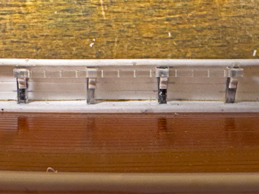
The pin-rails are 2.2 mm wide strips cut from 0.8 mm thick acrylic sheet. The holes were drilled using the micro-milling machine as a coordinate drill to get the distances right. The outer edges of the pin-rails were rounded as can be seen on many prototype photographs. The inner edges were notched for the bulwark stanchions on the filing-machine.

Cutting the notches for the stanchions on the filing-machine

Cutting the notches for the stanchions on the filing-machine
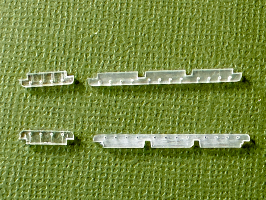
Collection of pin-rails
Pin-rails loosely attached at their designated location
To be continued �
Pin-rails
Another delay in actual shop-work was caused that I first had to work out were the pin-rails would go and how many pins they have to have to provide the necessary belaying points.
Drilling the pin-rails using the micro-mill as a coordinate drilling machine
The pin-rails are 2.2 mm wide strips cut from 0.8 mm thick acrylic sheet. The holes were drilled using the micro-milling machine as a coordinate drill to get the distances right. The outer edges of the pin-rails were rounded as can be seen on many prototype photographs. The inner edges were notched for the bulwark stanchions on the filing-machine.
Cutting the notches for the stanchions on the filing-machine
Cutting the notches for the stanchions on the filing-machine
Collection of pin-rails
Pin-rails loosely attached at their designated location
To be continued �
Eberhard
Former chairman Arbeitskreis historischer Schiffbau e.V. (German Association for Shipbuilding History)
--------------------------------------------------------------------------------------------------------------------------------------------------------------------------------------------
Former chairman Arbeitskreis historischer Schiffbau e.V. (German Association for Shipbuilding History)
--------------------------------------------------------------------------------------------------------------------------------------------------------------------------------------------
-
wefalck
- Posts: 2079
- Joined: Wed Sep 28, 2011 12:04 pm
- Location: Paris
- Contact:
Re: Pomeranian Rahschlup 1846 � 1/160 scale � Baltic trader
Pin-rails 2
As can be seen on drawings and old photographs, the pin-rails often rested on consoles attached to the bulwark stanchions for added strength. As about a dozen were needed, they were ‘mass-produced’ from a shaped styrene profile.
Milling the profile for the consoles to support the pin-rails
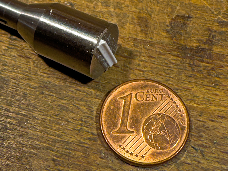
The shaped profile for the consoles
A 1.5 mm x 1 mm rod was stuck to a small ‘wax-chuck’ on the micro-milling machine with doubled-sided mounting tape. The rod was then oriented exactly parallel to the axis of the cross-slide and a hollow milled with a 1.5 mm ball-end burr.
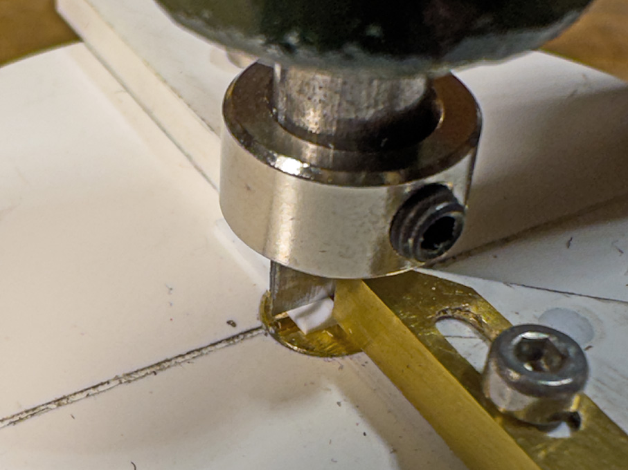
Slicing off consoles with the micro-guillotine
The edges were rounded with a fine file. This profiled rod was then transferred to the newly built micro-guillotine and slices of 0.7 mm thickness cut off. These miniature consoles then were stuck to the underside of the pin-rails. Once painted, they will be attached as units to the bulwarks.
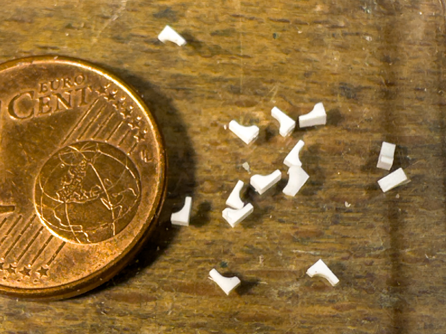
Collection of consoles
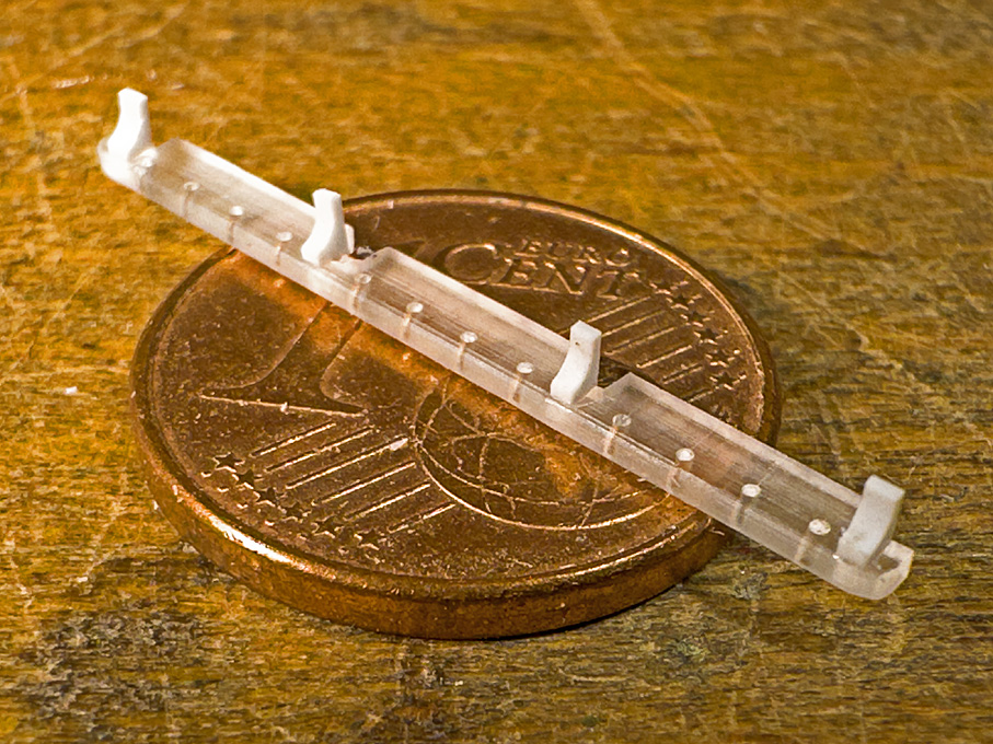
Consoles cemented to a pin-rail
Micro-Guillotine
The micro-guillotine was constructed around a part-machined cast-iron blank for a staking tool I found on ebay. Originally, I intended to fabricate all parts from steel, but I could not obtain a suitable blank for the rotating table and neither had the right steel bars in stock. So, for the time being at least, the parts were fabricated from 3 mm ABS sheet that I happened to have.
The cutting blade is a shortened chisel-shaped scalpel-blade. It is set into an exactly fitting slot in the 6 mm steel runner and secured with a steel ring. The knob on the runner is an old bakelite instrument knob. The 6 mm wide blade restricts the cutting capacity to 3 mm for 90° cuts and correspondingly less for cuts at an angle. This is a conscient restriction, as this tool is really meant to only cut parts up to 2 mm by 2 mm cross-section.

To cut at an angle, the plate is turned, rather than the cutter as in other designs. The narrow gap between the guides ensures that also very small parts can be cut. Their length can be set by the adjustable brass stop.

To be continued …
As can be seen on drawings and old photographs, the pin-rails often rested on consoles attached to the bulwark stanchions for added strength. As about a dozen were needed, they were ‘mass-produced’ from a shaped styrene profile.
Milling the profile for the consoles to support the pin-rails
The shaped profile for the consoles
A 1.5 mm x 1 mm rod was stuck to a small ‘wax-chuck’ on the micro-milling machine with doubled-sided mounting tape. The rod was then oriented exactly parallel to the axis of the cross-slide and a hollow milled with a 1.5 mm ball-end burr.
Slicing off consoles with the micro-guillotine
The edges were rounded with a fine file. This profiled rod was then transferred to the newly built micro-guillotine and slices of 0.7 mm thickness cut off. These miniature consoles then were stuck to the underside of the pin-rails. Once painted, they will be attached as units to the bulwarks.
Collection of consoles
Consoles cemented to a pin-rail
Micro-Guillotine
The micro-guillotine was constructed around a part-machined cast-iron blank for a staking tool I found on ebay. Originally, I intended to fabricate all parts from steel, but I could not obtain a suitable blank for the rotating table and neither had the right steel bars in stock. So, for the time being at least, the parts were fabricated from 3 mm ABS sheet that I happened to have.
The cutting blade is a shortened chisel-shaped scalpel-blade. It is set into an exactly fitting slot in the 6 mm steel runner and secured with a steel ring. The knob on the runner is an old bakelite instrument knob. The 6 mm wide blade restricts the cutting capacity to 3 mm for 90° cuts and correspondingly less for cuts at an angle. This is a conscient restriction, as this tool is really meant to only cut parts up to 2 mm by 2 mm cross-section.
To cut at an angle, the plate is turned, rather than the cutter as in other designs. The narrow gap between the guides ensures that also very small parts can be cut. Their length can be set by the adjustable brass stop.
To be continued …
Eberhard
Former chairman Arbeitskreis historischer Schiffbau e.V. (German Association for Shipbuilding History)
--------------------------------------------------------------------------------------------------------------------------------------------------------------------------------------------
Former chairman Arbeitskreis historischer Schiffbau e.V. (German Association for Shipbuilding History)
--------------------------------------------------------------------------------------------------------------------------------------------------------------------------------------------
-
wefalck
- Posts: 2079
- Joined: Wed Sep 28, 2011 12:04 pm
- Location: Paris
- Contact:
Re: Pomeranian Rahschlup 1846 � 1/160 scale � Baltic trader
Pin-rails post-script
When trying to fit the pin-rail with the consoles attached, I realised that I had overlooked a point: the tumble-home of the bulwark. This means that the angle between the pin-rails and the bulwark-stanchions is not 90°, but is a slightly obtuse angle of about 100°.
In consequence, I had to remake the consoles with this angle. As the process is essentially the same as described in the previous post, I am only showing a picture of the final result.
Pin-rail on consoles affixed temporarily
Another small tool-making digression
Milling the above profile required that the stock is oriented perfectly parallel to the X-axis of the micro-milling machine. While orienting the little vice is quite easy with the help of squares, orienting the stock on the face-plate would normally require tramming it in with a lever-gauge. The problem is that the lever gauges are far too big for the little milling machine. So far, I have eye-balled it with a pointed cutter in the spindle and some light test-cut to verify. This has been somewhat time-consuming and unsatisfactory.
Thinking about the problem, I remembered the so-called ‘wiggler’ (https://www.instructables.com/Wiggler-C ... the-Lathe/) and designed a tool based on the same principle. It is basically a stick that is pivoted at some point along its length, so that it can move freely at an angle. There is longer and a shorter end. The latter is brought into touch with the workpiece and any movement is amplified by the longer end.
I miniaturised this to a total length of 33 mm so that it fits easily between the milling spindle and the cross-slide. It consists of a piece of 6 mm diameter aluminium rod, that is turned down at one end to 2.4 mm to fit into a collet of that size. The diameter was chosen, because it is the shank diameter of the common burrs that I often use as milling cutters. That saves changing the collet after tramming.
Mini-lever-gauge and its ‘mechanism’ (right)
The rod is bored out 3 mm along most of its length and a 4 mm recess of 1.5 mm depth is turned in. This recess takes up a disc that has been punched out of a section of some polyethylene tubing. The feeler lever is an ordinary clothes pin, the head of which has been turned concentric (the stamping process of the pin production does not lead to completely concentric heads). At the upper end of the bore, a section of the aluminium rod is milled down to half the diameter, allowing to observe the movement the pin in this window.
The polyethylene disc is secured in the recess with a drop of general-purpose glue and the pin pushed through it concentrically until the pointed end arrives at the milled-out section. The flat has a few lines engraved to be able to better judge the movement of the point. With this the little tool is complete
In use the pin-head is brought into contact with the workpiece and the slide moved a tad in until the point coincides with one of the lines. When running up and down the workpiece edge, one observes the movement of the point and adjusts the angle of the workpiece until the point remains steady.
Tramming the mini-vice with the aid of the lever-gauge
The tool is perhaps a bit crude and not as sensitive as a commercial lever gauge, but it serves the purpose.
To be continued …
Eberhard
Former chairman Arbeitskreis historischer Schiffbau e.V. (German Association for Shipbuilding History)
--------------------------------------------------------------------------------------------------------------------------------------------------------------------------------------------
Former chairman Arbeitskreis historischer Schiffbau e.V. (German Association for Shipbuilding History)
--------------------------------------------------------------------------------------------------------------------------------------------------------------------------------------------
-
wefalck
- Posts: 2079
- Joined: Wed Sep 28, 2011 12:04 pm
- Location: Paris
- Contact:
Re: Pomeranian Rahschlup 1846 � 1/160 scale � Baltic trader
Cleats and Bollards
In addition to belaying pins, also various types of cleats are distributed around the ship. Their type and location had to be reconstructed from various sources, such as models and early photographs. On paintings of such vessels, they are generally not visible.
The first type concerns very large cleats that stretch across two bulwark stanchions. They are used for belaying heavy ropes, such as the main sheet. If they have a fairlead in middle, they also serve as mooring cleats.
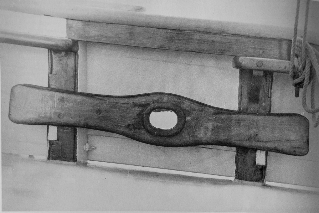
Mooring cleat (old photograph from unidentified book)
The photograph was imported into my 2D CAD program (EazyDraw) and the outline traced and scaled to size. This served as the basis for the laser-cutting file. Material for two cleats was cut. The cleats are laminated from four layers of Canson-paper (if I had a more powerful laser, of course, they could have been cut from some 0.6 mm thick material in one go). The resulting part was finally filed to shape. The fairlead is a copper rivet.
The completed mooring cleats
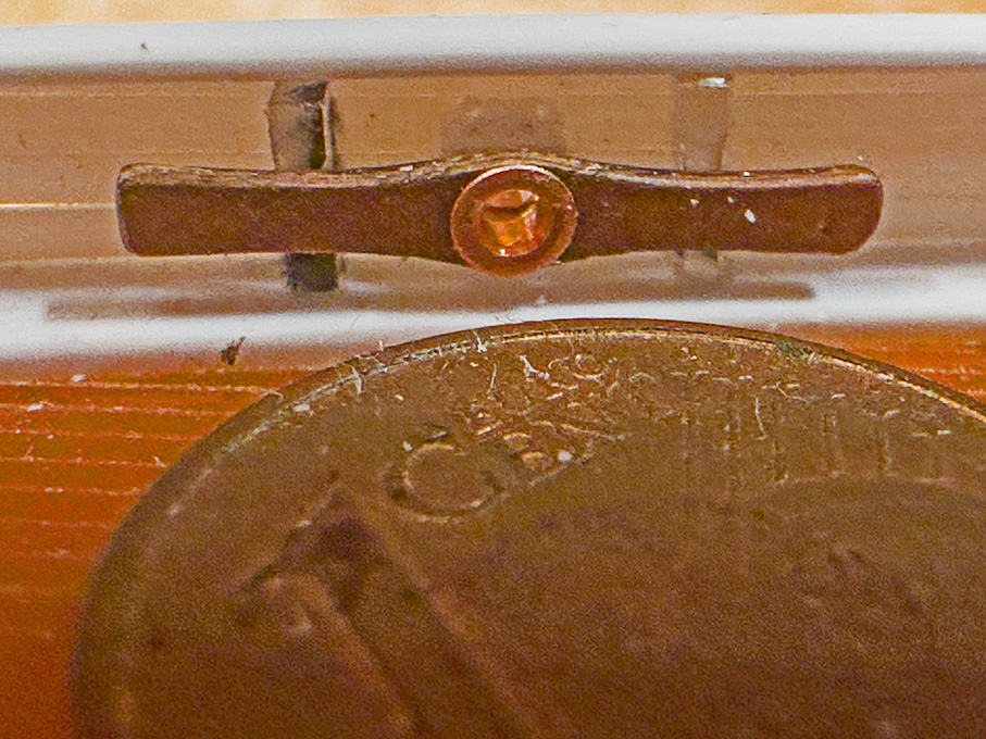
I am not sure, whether the pipe of the fairlead is in some way supported in the space between the cleat and the bulwark planking. I have not been able to find any photographs that show this detail. However, for practical reason I inserted a square piece of polystyrene with an appropriate hole drilled through. This allows me to insert a shortened hollow rivet from each side and hide the seam conveniently. As the cleats will be represented in varnished wood, as can be seen on the above photograph and various models, it allows me to locate the cleats after all the painting is done.

Fairlead from the outside
Looking at the close-up photographs, I think the fairleads should have been turned a bit smaller on the outside diameter, but I am going to leave them like this. I also realised that my planking looks pretty awful and needs to be worked over …
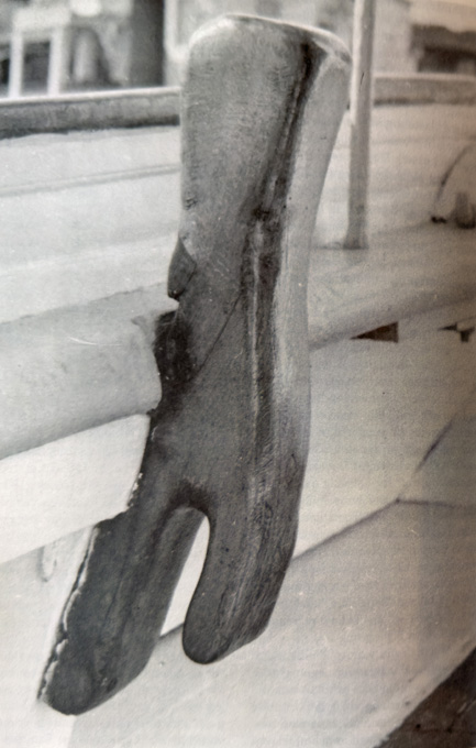
There are also several heavy cleats needed to belay for instance the backstays or the ropes used to secure the anchors. They are of a type that seems to have fallen out of modern use, namely half-cleats combined with a bollard
https://www.maritima-et-mechanika.org/m ... mpe-72.jpg
Combination of bollard and half-cleat (old photograph from unidentified book)
The shape was developed in the 2D CAD program and measurements for the machining derived from this. The rough shape was milled out of some 1 mm x 3 mm polystyrene profile. In fact the enveloppe is only 1 x 1.5 mm, but the additional material is needed initially to be able to hold the part in the vice.
Milling the rough shape of the bollard/half-cleat combination
Milling the rough shape of the bollard/half-cleat combination – close-up
The final shape was given with the aid of various metal- and diamond-files and scraping to remove the fuzz from filing. I am using for this a ‘French’ type of pin-vise, on which I replaced the brass jaws with ones made from wood.
One should note that, as they will attach to bulwark stanchions, their back has to be slightly curved.
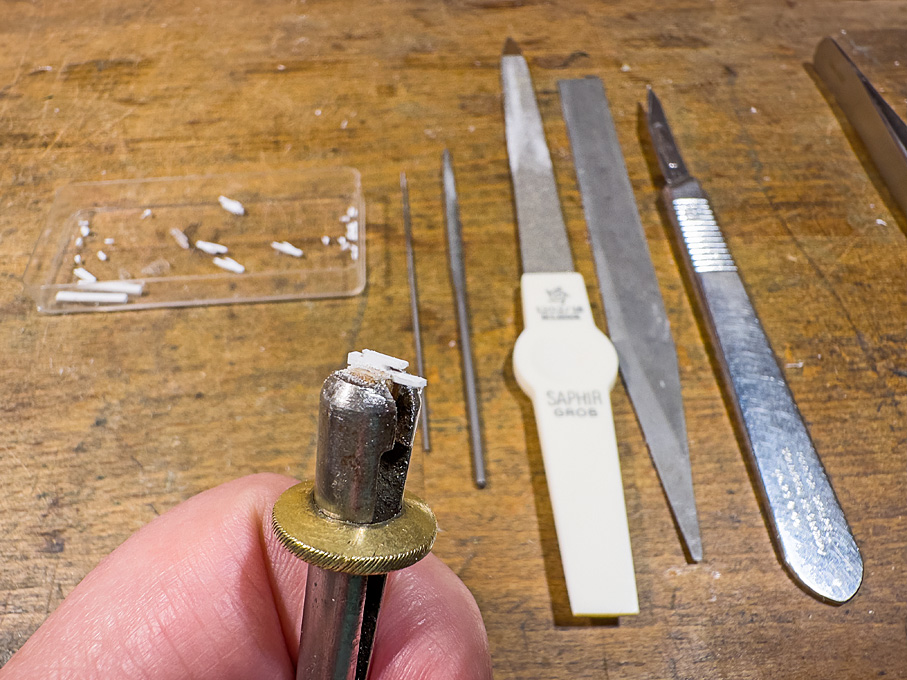
Filing a cleat to shape
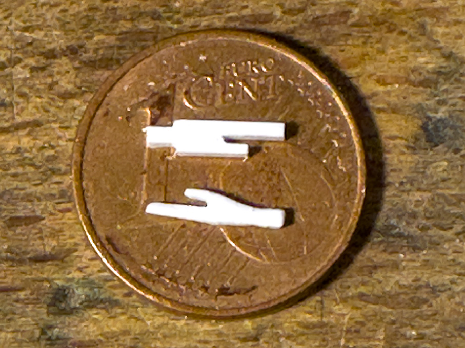
Roughed-out cleat (top) and finished cleat (bottom)
To be continued …
In addition to belaying pins, also various types of cleats are distributed around the ship. Their type and location had to be reconstructed from various sources, such as models and early photographs. On paintings of such vessels, they are generally not visible.
The first type concerns very large cleats that stretch across two bulwark stanchions. They are used for belaying heavy ropes, such as the main sheet. If they have a fairlead in middle, they also serve as mooring cleats.
Mooring cleat (old photograph from unidentified book)
The photograph was imported into my 2D CAD program (EazyDraw) and the outline traced and scaled to size. This served as the basis for the laser-cutting file. Material for two cleats was cut. The cleats are laminated from four layers of Canson-paper (if I had a more powerful laser, of course, they could have been cut from some 0.6 mm thick material in one go). The resulting part was finally filed to shape. The fairlead is a copper rivet.
The completed mooring cleats
I am not sure, whether the pipe of the fairlead is in some way supported in the space between the cleat and the bulwark planking. I have not been able to find any photographs that show this detail. However, for practical reason I inserted a square piece of polystyrene with an appropriate hole drilled through. This allows me to insert a shortened hollow rivet from each side and hide the seam conveniently. As the cleats will be represented in varnished wood, as can be seen on the above photograph and various models, it allows me to locate the cleats after all the painting is done.
Fairlead from the outside
Looking at the close-up photographs, I think the fairleads should have been turned a bit smaller on the outside diameter, but I am going to leave them like this. I also realised that my planking looks pretty awful and needs to be worked over …
There are also several heavy cleats needed to belay for instance the backstays or the ropes used to secure the anchors. They are of a type that seems to have fallen out of modern use, namely half-cleats combined with a bollard
https://www.maritima-et-mechanika.org/m ... mpe-72.jpg
Combination of bollard and half-cleat (old photograph from unidentified book)
The shape was developed in the 2D CAD program and measurements for the machining derived from this. The rough shape was milled out of some 1 mm x 3 mm polystyrene profile. In fact the enveloppe is only 1 x 1.5 mm, but the additional material is needed initially to be able to hold the part in the vice.
Milling the rough shape of the bollard/half-cleat combination
Milling the rough shape of the bollard/half-cleat combination – close-up
The final shape was given with the aid of various metal- and diamond-files and scraping to remove the fuzz from filing. I am using for this a ‘French’ type of pin-vise, on which I replaced the brass jaws with ones made from wood.
One should note that, as they will attach to bulwark stanchions, their back has to be slightly curved.
Filing a cleat to shape
Roughed-out cleat (top) and finished cleat (bottom)
To be continued …
Eberhard
Former chairman Arbeitskreis historischer Schiffbau e.V. (German Association for Shipbuilding History)
--------------------------------------------------------------------------------------------------------------------------------------------------------------------------------------------
Former chairman Arbeitskreis historischer Schiffbau e.V. (German Association for Shipbuilding History)
--------------------------------------------------------------------------------------------------------------------------------------------------------------------------------------------