Something New

For discussion of Computer Modeling. Virtual Ship building. Computer Aided Design and Drafting, CAD/CAM, CGI, and the techniques behind them.

Moderator: ArizonaBB39

TommyL
Posts: 292
Joined: Mon Sep 19, 2005 8:59 pm

Something New

Post by TommyL »

Hey its me again. Ive finally scratched the surface of CAM wich makes me happy. :eyebrows:

Here is a sample below. I failed to get the tool path I want but atleast G Code was generated for a change :thumbs_up_1: I had it right then I had to tinker some more...........stupid.

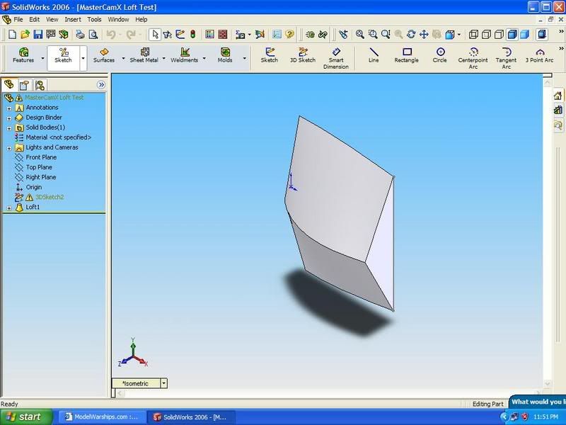
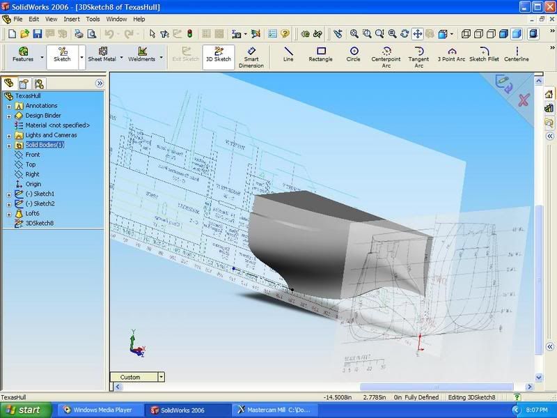
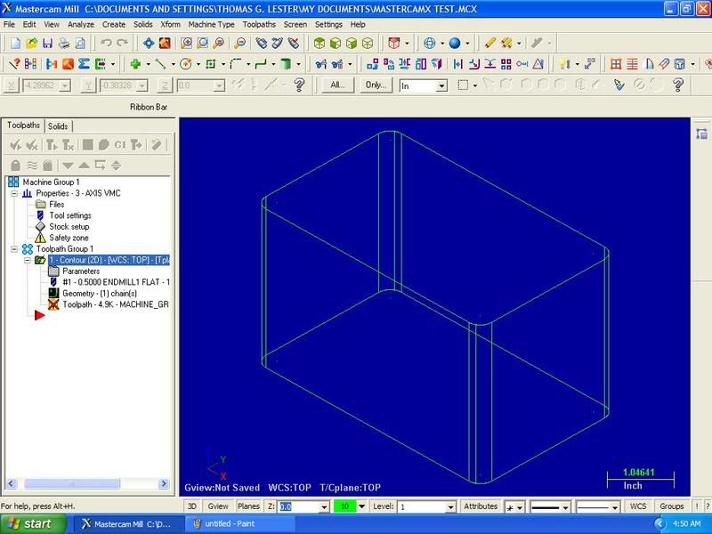
This is a solid created through CAD. although it apears as a wire frame in CAM.
Image

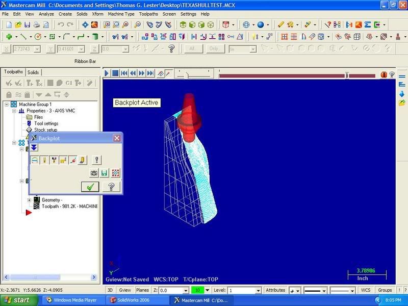
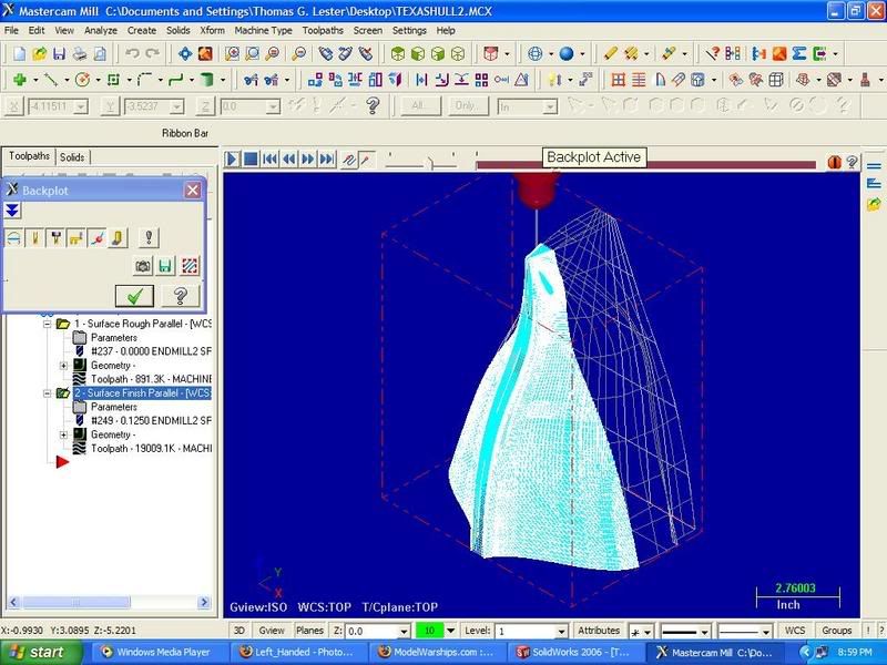
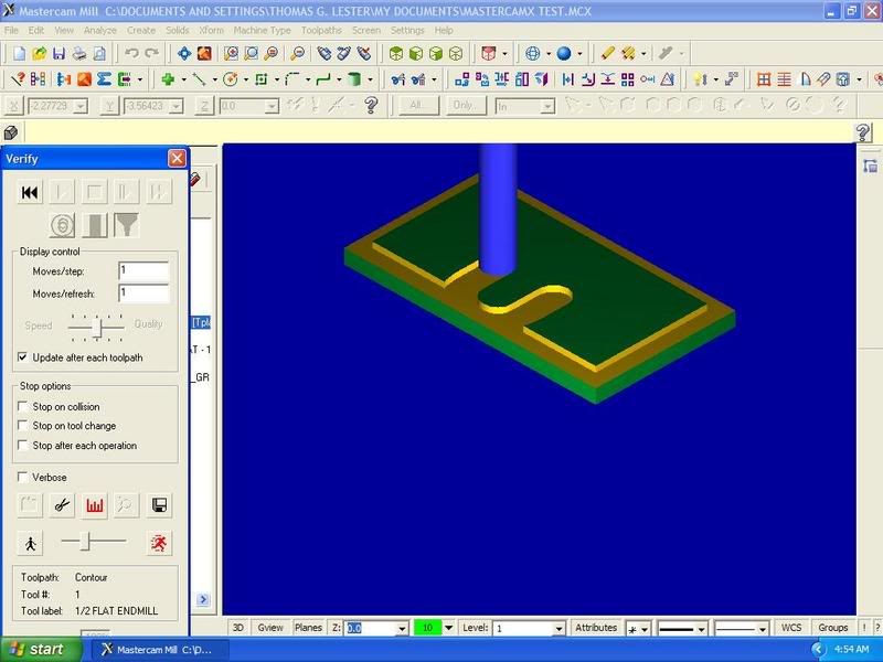
Here is a screen shot of the tool path simulation. As you can see it started the contour path inside the part and not around the perimeter.
Image

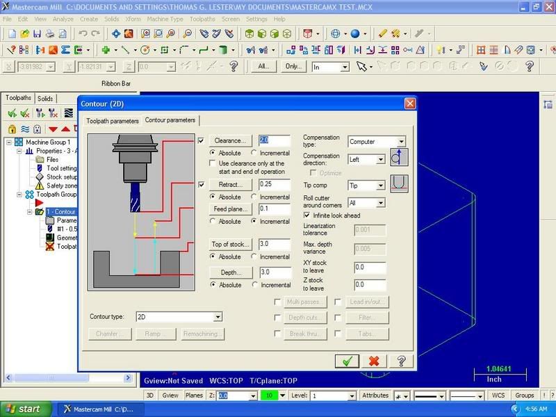
Lastly here is an example tool lenght and offset.
Image

Here is the G Code that the machine tool reads:
%
O0000(TEST CNC PROGRAM)
(DATE=DD-MM-YY - 17-10-06 TIME=HH:MM - 04:47)
(MCX FILE - C:\DOCUMENTS AND SETTINGS\THOMAS G. LESTER\MY DOCUMENTS\MASTERCAMX TEST.MCX)
(NC FILE - C:\DOCUMENTS AND SETTINGS\THOMAS G. LESTER\DESKTOP\ENTERTAINMENT\TEST CNC PROGRAM.TXT)
(MATERIAL - ALUMINUM INCH - 2024)
( T1 | 1/2 FLAT ENDMILL | H1 )
N100 G20
N102 G0 G17 G40 G49 G80 G90
/ N104 G91 G28 Z0.
/ N106 G28 X0. Y0.
/ N108 G92 X10. Y10. Z10.
N110 T1 M6
N112 G0 G90 X.2668 Y-.201 S3056 M3
N114 G43 H1 Z3.1 M8
N116 G1 Z3. F6.42
N118 Y-.701 F48.9
N120 G2 X-.2332 Y-1.201 R.5
N122 G1 X-2.4832
N124 Y1.299
N126 X2.0168
N128 Y-1.201
N130 X-.2332
N132 G2 X-.7332 Y-.701 R.5
N134 G1 Y-.201
N136 Z3.1 F6.42
N138 M5
N140 G91 G0 G28 Z0. M9
N142 G28 X0. Y0.
N144 M30
%

This is just simple 2D milling. I hope to be doing 3D milling soon.

TommyL.
User avatar
Timmy C
Posts: 12437
Joined: Mon Jan 10, 2005 6:00 pm
Location: Ottawa, Canada

Post by Timmy C »

Best of luck with your endeavour :thumbs_up_1:
De quoi s'agit-il?
TommyL
Posts: 292
Joined: Mon Sep 19, 2005 8:59 pm

Post by TommyL »

Ok here is my next project. This is nothing impressive but please bear with me. I am trying to learn CAD as well as CAM at the same time. Right now I do not have time or the funds for training so Im learning by trail and error. All my spare cash is going tward buying my machine.

The reason I created this drawing was to work with lofted surfaces like a ships hull.

I messed with this drawing last nite to create a 3 axis tool path and had little to no luck getting what I wanted.

Here is the simple test drawing:
Image

TommyL.
TommyL
Posts: 292
Joined: Mon Sep 19, 2005 8:59 pm

Post by TommyL »

Ok,

I found out that if you select points in the wrong order it will generate a tool path completely different from what you want. My last attempt at doing so made a path that would have crashed for sure.

TommyL.
User avatar
kennylibben
Posts: 1065
Joined: Tue Jan 11, 2005 7:25 am
Location: I live in Off-Topic...
Contact:

Post by kennylibben »

interesting, just yesterday i was wondering how things were going with machining...
It's not who you are, but what you do that defines you.
TommyL
Posts: 292
Joined: Mon Sep 19, 2005 8:59 pm

Post by TommyL »

Only $1500.00 more to go Kenny but thats another post. I see this section is for CAD/CAM so I figured I would add some CAM samples in. Speaking of that here is an interesting free program I found a few nites ago:

http://www.mecsoft.com/Mec/Products/FreeMill.shtml
Available file imports include: VisualMill, Rhino, STL, VRML. Only works for Milling ( Free Mill )

I found some more stuff but its geared tward those that have machine tools to take advantage of the software.

TommyL.
User avatar
Mark Petersen
Posts: 96
Joined: Mon Jan 10, 2005 5:30 pm
Location: Kenosha, no, not the Pass the other one

Post by Mark Petersen »

It's been a while since I wrote code for myself. G Code can be cumbersome at times but if you have a problem it can easier to figure out than a conversation programing system. Trust me I know from experience. When self teaching its all about small steps.
It's my $.02, not yours. Feel free to spend yours. I won't stop you
TommyL
Posts: 292
Joined: Mon Sep 19, 2005 8:59 pm

Post by TommyL »

Yep Mark,

Im still learning in baby steps. The saying about crawling before running comes to mind.

I did find a tutorail disk that might be worthwhile..........not sure yet.
TommyL
Posts: 292
Joined: Mon Sep 19, 2005 8:59 pm

Post by TommyL »

Hey,

I hope everything is still going well.

Anyway I have something new to share so here is an update.

I've finally got a good grasp on simple 2D machine programing. It will not work for doing a complex ship hull with all the convex curves but it's a start for now that should open the door for more complex stuff.

Here it is:
Image

Atleast I can produce a keel, hull frames, basic superstructure, and decks.

TommyL.
User avatar
kennylibben
Posts: 1065
Joined: Tue Jan 11, 2005 7:25 am
Location: I live in Off-Topic...
Contact:

Post by kennylibben »

cant wait to see some of your work!
It's not who you are, but what you do that defines you.
TommyL
Posts: 292
Joined: Mon Sep 19, 2005 8:59 pm

Post by TommyL »

More Progress!

Now for something even more complex. I have finally generated a 3D CNC tool path.

Here is the drawing in Solidworks. I messed up by setting everything up on the wrong plane. Since I choose the wrong plane it comes up wrong in MasterCAM. This would be fine if I had a VMC (Vertical Machine Center) with around 20" Z axis travel but I do not. My small Millport cnc on has 5" Z travel..........You will see below.
Image
See the Z axis is running horizontal? Thats no good.

Here is the model rendered as a wire frame to generate a tool path.
Image
See how hull section should have been laid on its side for a better tool path? Any way this part would be cut with a 1/4" end mill for the rough cut followed by a smaller 1/8" end mill. I chose to use smaller tools because I hate having to sand/blend so why not make the machine create a smooth finish. :lol_1:

I have yet to pick up my machine. When I do I can show actual pictures of automated milling in progress. For now the programing side I hope you all enjoy.........I know I do.

TommyL.
Last edited by TommyL on Sun Mar 11, 2007 9:43 pm, edited 2 times in total.
TommyL
Posts: 292
Joined: Mon Sep 19, 2005 8:59 pm

Post by TommyL »

Here is the model redone a little.

Image
I managed to rotate the part for better viewing and programed for a smaller finish cutter. This will give a better surface finish.

I hope you guys can enjoy this as much as I do. This whole project has almost drove me to the mental hospital and hit my wallet hard. I'm so happy that this isn't looking like a waste of time anymore. Knowing this will help me so much at work. Maybe I can be a little more worth while. The machine shop I work for hired me on with no experience at running cnc machinery or cad/cam programing skills. On my first day about a year and a half ago they put me on their new mill that cost them a great deal.

This should also help me in my scratch modeling also. I have now real skills in modeling to speak of so I need a machine to do the work for me. :lol_1: It may sound like I'm bashing myself and being Doctor Doom but its the truth.

Right now is a high point for me. In a section of the forum dominated by cad I'm honored to to bring in the cam side to make this section really cover what its name says, cad/cam.

TommyL.
User avatar
kennylibben
Posts: 1065
Joined: Tue Jan 11, 2005 7:25 am
Location: I live in Off-Topic...
Contact:

Post by kennylibben »

shizenhauser!


A-Mazing Tommy!


And quit bashing yourself, you always freak-a-leak on me when for it so i'm gonna smack you if you dont stop!
It's not who you are, but what you do that defines you.
User avatar
ARH
Posts: 2557
Joined: Mon Jan 10, 2005 10:52 am
Location: Land of the Cheshire cat

Post by ARH »

Well Tommy, life can be so good when a plan comes together, nice to see you enjoying yourself and doing wonders at it, far beyond my capabilities, well son keep up the good work . dad :wave_1: :wave_1: :thumbs_up_1:
Simple but effective.
User avatar
ARH
Posts: 2557
Joined: Mon Jan 10, 2005 10:52 am
Location: Land of the Cheshire cat

Post by ARH »

kenny, dont be smacking tommy, or we will send in the RN, :lol_3: :lol_3:
Simple but effective.
User avatar
kennylibben
Posts: 1065
Joined: Tue Jan 11, 2005 7:25 am
Location: I live in Off-Topic...
Contact:

Post by kennylibben »

your pathetic RN doesn't scare me, you deserted them and then they all broke up. Besides, i have a feeling Tommy would join the pirates if need be.


And you dont know the full story, Tommy threatens me if i say my models aren't that good... i'm only returning the favor.
It's not who you are, but what you do that defines you.
User avatar
ARH
Posts: 2557
Joined: Mon Jan 10, 2005 10:52 am
Location: Land of the Cheshire cat

Post by ARH »

:lol_3: :lol_3: :lol_3: :heh: :heh: :lol_spit_1: :lol_spit_1: :lol_spit_1:
Simple but effective.
User avatar
kennylibben
Posts: 1065
Joined: Tue Jan 11, 2005 7:25 am
Location: I live in Off-Topic...
Contact:

Post by kennylibben »

:scratch:
It's not who you are, but what you do that defines you.
TommyL
Posts: 292
Joined: Mon Sep 19, 2005 8:59 pm

Post by TommyL »

Hello again.

I've found multiple tool collisions while running the backplot simulation. To avoid this problem I aligned the model for the Z axis to clear machines spindle when it ramps down to cut into the part. Doing so fixed a few problems but some still remain. I think I have a solution that I'll try to post later on.

TommyL.
TommyL
Posts: 292
Joined: Mon Sep 19, 2005 8:59 pm

Post by TommyL »

Ok,

I'm still working on the tool collisions so that will have to wait a while longer.

Hopefully in a few more days everyone can see a cut piece. Just a few things to work out now such as wiring 220 single phase service to the machine,tinker with file transfers, buy some tooling holders, clamps and a few more goodies. This way I can atleast attempt to show what the CAM side can do for those that have never seen it. For those that already know I can bore the heck out of them or make them say, "Why did that idiot do it that way?!"

TommyL.
Post Reply

Return to “Virtual Ship Modeling”