Beautiful work Micheal!
And educational to boot. I remember reading logs of the period, where Commanders would complain about how they lost up to 30% power in rough seas; and now I know why. Every time a steam ship would plunge down a swell, those relief valve weights would rise and vent needed pressure! Keep up the good work. Cant wait to see it all together.
USS Monitor turret drive machinery
Moderator: ArizonaBB39
-
Fritz

- Posts: 125
- Joined: Fri Aug 04, 2006 12:03 pm
- Location: Salem, MA, USA
Re: USS Monitor turret drive machinery
Best Regards
Fritz K.
Fritz K.
-
DrPR

- Posts: 1689
- Joined: Sun Mar 07, 2010 12:01 am
- Location: Corvallis, Oregon, USA
- Contact:
Re: USS Monitor turret drive machinery
Michael,
For my full ship CAD models I cheat a lot on things like threads. With file sizes approaching a gigabyte without putting threads on all of the thousands of bolts, screws and nuts, it is totally impractical to include threads. However, I don't want these things to look like plain cylinders on not-too-close inspection. The same is true of cables, wire runs, etc.
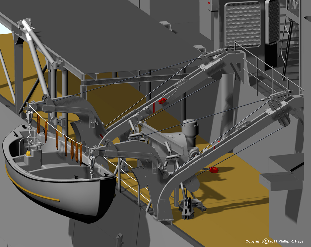
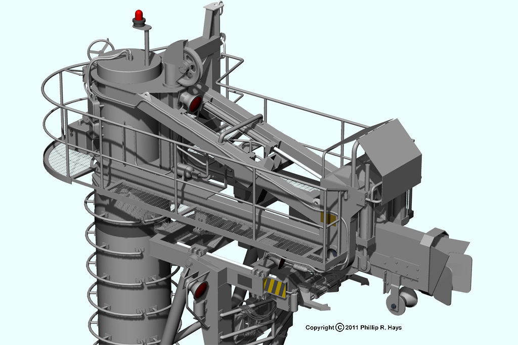
My solution is to use 8 and 12 sided "cylinders." Again, these are only in places that aren't visible close up in the images. It is amazing how much an 8 sided "cable" looks like a twisted wire cable, a life line or an electrical cable run when viewed with shading from a moderately close distance.
Here are some examples. All of the cables, wiring, life lines and ropes are 12-sided extrusions. This produces a much smaller file size increase than an extruded circle. None of the bolts have threads.
http://www.okieboat.com/Copyright%20ima ... 24%20C.jpg
http://www.okieboat.com/Copyright%20ima ... 24%20C.jpg
Phil
For my full ship CAD models I cheat a lot on things like threads. With file sizes approaching a gigabyte without putting threads on all of the thousands of bolts, screws and nuts, it is totally impractical to include threads. However, I don't want these things to look like plain cylinders on not-too-close inspection. The same is true of cables, wire runs, etc.
My solution is to use 8 and 12 sided "cylinders." Again, these are only in places that aren't visible close up in the images. It is amazing how much an 8 sided "cable" looks like a twisted wire cable, a life line or an electrical cable run when viewed with shading from a moderately close distance.
Here are some examples. All of the cables, wiring, life lines and ropes are 12-sided extrusions. This produces a much smaller file size increase than an extruded circle. None of the bolts have threads.
http://www.okieboat.com/Copyright%20ima ... 24%20C.jpg
http://www.okieboat.com/Copyright%20ima ... 24%20C.jpg
Phil
A collision at sea will ruin your entire day. Aristotle
-
mcg
- Posts: 201
- Joined: Thu Apr 28, 2005 8:46 pm
Re: USS Monitor turret drive machinery
Makes a lot of sense, Fritz. If the safety valves started blowing off steam in rough seas, it would affect not only the main engines but also the blower and other auxiliary engines. Could be if the USS Monitor had used spring loaded instead of weighted safety valves, she might have survived Hatteras.
Phil, many thanks for this technique. I thought a cylinder, because of its simplicity, would burn less memory. The octagon effect is intriguing and your wiring as I have often noticed, is phenomenal.
Now we are into the problem of plumbing the turret engines. Here is schematic representation from the Swedish museum overhead view, superimposed on the 3D model of the engines and gearbox.
The green is low pressure, exhaust steam. The red is high pressure steam from the boiler. What we can learn from this is just that the drawing is a schematic, not a pictorial. It shows short, direct paths that can be drawn with a pencil to indicate where the steam comes from and where it goes. The practical problem is that these lines run, for examples, straight through the crankshaft and the main spur gear. The real piping configuration must be different -- longer and more curved, probably flanking the gearbox and then looping down to the engines.
We have a couple of other clues.
One is the fanciful Harpers cartoon:
This shows what might be an intake conduit running outside the gearbox, high on the port side, and a couple of goofy, swoopy pipes running down to and converging at the level of the steam chest of the port side engine cylinder. This cartoon is very little help except that it gives us a real world artist's subjective impression -- he was in the galley, and he actually saw the thing.
The other image is the photo of the turret engines of the Comanche:
The photo shows the intake and exhaust pipes doubling back in 180 degree curves from the steam chest. The other cylinder follows the same pattern.
In trying to work this out I will take the initial approach that the steam lines run above the engine, at about the same vertical level at which they enter the galley. Another option would be to route the steam pipes down underneath the gearbox, but I think this would take too big a bite out of the crews' space -- notably that of the cook.
I have sought the counsel of Rich Carlstedt on the steam system.
http://www.stationarysteam.com/
http://www.stationarysteam.com/u.s.s.-m ... llery.html
No one -- no one -- knows the USS Monitor as Rich does. He has been most helpful in suggesting in detail how the steam system valving and drain cocks were most probably worked out for the turret engines. Many thanks to Rich and to Devin for helping me get in touch with him!
Phil, many thanks for this technique. I thought a cylinder, because of its simplicity, would burn less memory. The octagon effect is intriguing and your wiring as I have often noticed, is phenomenal.
Now we are into the problem of plumbing the turret engines. Here is schematic representation from the Swedish museum overhead view, superimposed on the 3D model of the engines and gearbox.
We have a couple of other clues.
One is the fanciful Harpers cartoon:
The other image is the photo of the turret engines of the Comanche:
- 3a36217r to crop.jpg (20.2 KiB) Viewed 7745 times
In trying to work this out I will take the initial approach that the steam lines run above the engine, at about the same vertical level at which they enter the galley. Another option would be to route the steam pipes down underneath the gearbox, but I think this would take too big a bite out of the crews' space -- notably that of the cook.
I have sought the counsel of Rich Carlstedt on the steam system.
http://www.stationarysteam.com/
http://www.stationarysteam.com/u.s.s.-m ... llery.html
No one -- no one -- knows the USS Monitor as Rich does. He has been most helpful in suggesting in detail how the steam system valving and drain cocks were most probably worked out for the turret engines. Many thanks to Rich and to Devin for helping me get in touch with him!
Last edited by mcg on Tue Dec 17, 2013 12:11 pm, edited 4 times in total.
-
Devin

- Posts: 2497
- Joined: Mon Jan 10, 2005 10:46 am
- Location: Hoboken, NJ
- Contact:
Re: USS Monitor turret drive machinery
Excellent. Glad you and Rich are talking!
I just made my hotel room reservation for the Nationals in Hampton next August. Going to make a week of it and spend a chunk of that time at the Mariner's doing research.
Amazing work on this. Really fantastic!
I just made my hotel room reservation for the Nationals in Hampton next August. Going to make a week of it and spend a chunk of that time at the Mariner's doing research.
Amazing work on this. Really fantastic!
We like our history sanitized and theme-parked and self-congratulatory, not bloody and angry and unflattering. - Jonathan Yardley
-
DrPR
- Posts: 1689
- Joined: Sun Mar 07, 2010 12:01 am
- Location: Corvallis, Oregon, USA
- Contact:
Re: USS Monitor turret drive machinery
Michael,
I should have said that the eight and twelve sided "cylinders" use less memory in the program I use (DesignCAD). It is not a parametric CAD program, but works like AutoCAD in generating a what-you-see-is-what-you-get drawing with all surfaces generated in the file. This may not be true in other programs.
For simple objects a true cylinder may use less memory. But when a circle is extruded through a curved path (like piping, wire runs, ropes and cables or life lines) the result is not a cylinder, but an object with complex curved surfaces. The program generates a series of intermediate "slices" along the curved path and patches these together with some number of planes to create a grid surface - so it really is not cylindrical. The default for DesignCAD is to put 120 planes around each section, and to put 100 sections between each point defining the curve - 12,000 planes between each point!
To illustrate the problem I once created a simple hand railing for an inclined ladder by extruding a circle along a curve using the program defaults - it added 13 Mbytes to the drawing! This was a long time ago on a machine that could work with drawings no larger than about 40 Mbytes - only three hand rails. That was when I learned to pay attention to file sizes. I redrew the hand rail using cylinders for the straight sections and swept 36 sided polygons for the curved parts, and it added only about 12 Kbytes, or about 1/1000 the memory use of the original, and looked just as good.
You can reset all of the program defaults to something sensible like 36 planes and 5 sections, or 180 planes between each point on the curve, and it will use 1/66 as much memory. Even this is just too many planes in drawings with dozens of cable runs. The defining curves for the cable extrusion will have dozens of points to get them to wrap around, through and over all the other stuff. For these I use 8 planes and one intermediate slice to get only 16 planes between each point. That's 1/750 as much memory useage as the default values.
For pipes I normally use 36 planes and 1 to 5 intermediate sections. Where cylindrical objects will be added or subtracted to create "T" and "Y" shapes and such I may use even more planes (up to 72) in order to get smooth joints.
Phil
A collision at sea will ruin your entire day. Aristotle
-
mcg
- Posts: 201
- Joined: Thu Apr 28, 2005 8:46 pm
Re: USS Monitor turret drive machinery
The improvement from 13 meg to 13k is phenomenal. Excellent technique. I will experiment with the program I am using and see what results.
This is a mock up of the turret engine inlet valve. It shows where I think Ericsson probably put it, in an out of the way niche behind the gearbox (and stove), between the boilers. The position is defined by that of the incoming high pressure steam line; and by the limits put on the available space by, for example, the swing of the crankshaft. I have rotated the crank in this test model to check for interference.
It is probably no accident that the valve is tucked out of the way, up high and in behind the cook's stove.
The turret was retracted to the deck and stowed most of the time, and it would have caused real problems if someone naievely walked up and turned the valve wheel and thus started the turret engines when the ship was underway and the turret was stowed.
High pressure steam passes up through the valve to a T-splitter. Exhaust steam converges to another T-nexus immediately above it. This is just a mock up and will change as the piping proceeds, but I think the position and size of the turret engine steam valve are about right. It is a scaled down replica of the main valve.
-
mcg
- Posts: 201
- Joined: Thu Apr 28, 2005 8:46 pm
Re: USS Monitor turret drive machinery
Rich Carlstedt and I have been corresponding about various problems in completing the turret engine model. As you probably know, Rich created this operating replica of the USS Monitor's main engine.
https://www.youtube.com/watch?v=VWn8gQ9Ykpk
For the turret engine project a major problem has been bearings -- specifically the crankcase and gearbox bearings. In an email Rich summarized the bearing types Ericsson used on the main engine. This summary has been very helpful to me and may also be helpful to other modelers, so with Rich's kind permission I am reproducing his emailed summary here:
"Ericsson used 3 metals and 6 different bearing applications on the main engine.
The bearing materials are:
Cast Iron- A great bearing material, but brittle
Bronze- which is nick named �brasses� ( erroneously )
Anti-attrition Metal � which is Babbitt metal
The application methods are :
Strap ends � AKA called Gib and Cotter -used on con rods/piston rods- Bronze
Pillow Blocks � Radial support for shafts-Bronze
Thrust Plates � used on Forward and Reverse engine direction -Cast Iron. Babbitt, and Bronze
Inserts- like an auto rod bearing- Bronze
Flanged Blocks �Enhanced pillow blocks to also take thrust loads-Bronze
Poured Bearings/Inserts � Babbitt castings
Also, every bearing is split into two pieces!"
The bearing type that seems most pertinent to the turret mechanism is a split flanged bearing. In the case of the turret engine crankcase this is a conjecture -- we have no very informative drawings. In the case of the gearbox it is pretty definite, since a split flanged bearing was clearly identified by Rich in a Stevens collection drawing.
Rich created a number of split flanged bearings for the main engine, as shown in this photo:
This photo of the engine frame, with two bearings installed, suggests how the bearings were secured.
Photos reproduced permission of Rich Carlstedt
More detail on the replica of the main engine of the USS Monitor is available on Rich's website, here:
http://www.stationarysteam.com/
A slide show of individual components is on Flickr, here:
http://www.flickr.com/photos/mjoat/sets ... 8938/show/
Note that although bearings of this type were called "brasses," they were actually bronze, something to bear in mind if you are doing a render.
https://www.youtube.com/watch?v=VWn8gQ9Ykpk
For the turret engine project a major problem has been bearings -- specifically the crankcase and gearbox bearings. In an email Rich summarized the bearing types Ericsson used on the main engine. This summary has been very helpful to me and may also be helpful to other modelers, so with Rich's kind permission I am reproducing his emailed summary here:
"Ericsson used 3 metals and 6 different bearing applications on the main engine.
The bearing materials are:
Cast Iron- A great bearing material, but brittle
Bronze- which is nick named �brasses� ( erroneously )
Anti-attrition Metal � which is Babbitt metal
The application methods are :
Strap ends � AKA called Gib and Cotter -used on con rods/piston rods- Bronze
Pillow Blocks � Radial support for shafts-Bronze
Thrust Plates � used on Forward and Reverse engine direction -Cast Iron. Babbitt, and Bronze
Inserts- like an auto rod bearing- Bronze
Flanged Blocks �Enhanced pillow blocks to also take thrust loads-Bronze
Poured Bearings/Inserts � Babbitt castings
Also, every bearing is split into two pieces!"
The bearing type that seems most pertinent to the turret mechanism is a split flanged bearing. In the case of the turret engine crankcase this is a conjecture -- we have no very informative drawings. In the case of the gearbox it is pretty definite, since a split flanged bearing was clearly identified by Rich in a Stevens collection drawing.
Rich created a number of split flanged bearings for the main engine, as shown in this photo:
More detail on the replica of the main engine of the USS Monitor is available on Rich's website, here:
http://www.stationarysteam.com/
A slide show of individual components is on Flickr, here:
http://www.flickr.com/photos/mjoat/sets ... 8938/show/
Note that although bearings of this type were called "brasses," they were actually bronze, something to bear in mind if you are doing a render.
Last edited by mcg on Wed Dec 18, 2013 9:29 am, edited 6 times in total.
-
Devin
- Posts: 2497
- Joined: Mon Jan 10, 2005 10:46 am
- Location: Hoboken, NJ
- Contact:
Re: USS Monitor turret drive machinery
Very cool you and Rich are working together. That man's knowledge of USS Monitor machinery is almost eerie.
We like our history sanitized and theme-parked and self-congratulatory, not bloody and angry and unflattering. - Jonathan Yardley
-
mcg
- Posts: 201
- Joined: Thu Apr 28, 2005 8:46 pm
Re: USS Monitor turret drive machinery
Thanks for putting us in touch, Devin.
With the bearing type understood, it was possible to model a more realistic crankcase. Here is the casting.
The split flanged bearing looks like this:
Here is an exploded view of the assembly, looking forward.
And looking aft:
Some bearings of this type used caps secured by studs, with the studs immobilized by wedges. Rich suggested that these caps should be secured using though bolts, which had greater strength than studs in that era. These bearing caps take significant loads from the engines. Here is the finished crankcase:
The deck beam from which the crankcase is suspended has been milled to make room for the flanged bearing. Still to be added are four lock washers of an unusual type. Here is the unit shown in the context of the gearbox frame.
Many thanks to Rich for his time and patient help in solving this. Michael
With the bearing type understood, it was possible to model a more realistic crankcase. Here is the casting.
-
mcg
- Posts: 201
- Joined: Thu Apr 28, 2005 8:46 pm
Re: USS Monitor turret drive machinery
The next bearing problem is the gearbox. The crankcase and gearbox were suspended from 10" x 10" overhead deck beams. Here is a view of the gearbox from below.
The lower bearing takes the weight of the shaft, spur gear, and a large pinion. The mounting for this bearing is straightforward. I put crossmember under the bar of the "H". I am not finding it in drawings but I think it needs to be there. Conjecture.
The upper bearing takes no weight, but it does take loads from the accelerations and decelerations of the gear train. It is assumed that the upper and lower bearings were identical split flanged bearings. The drawing for these is from the Stevens collection.
The upper bearing was mounted into the 10" square deck beam. Here is my guess at how it was done.
The split flanged bearing was mounted in this casting. The casting was mortised into the oak deck beam and bolted through it. The casting is 1.5 inches thick in the wings, and twice that deep in the middle where it supports the bearing. This technique of mortising and bolting castings and oak is consistent with several other structures, most notably the through-deck casting for the turret shaft.
This image shows the gears mounted on the shaft. It occurred to me to use an "L" for the casting, to provide greater strength to the beam, but since I am guessing I am inclined to keep the structure as simple as possible.
Detailing, adding in nuts and bolts. Admiral Porter, when he inspected the Monitor under construction, called this machinery "the coffee grinder."
Here it is with the engine restored. Changes to the crankcase and gearbox are complete. It should now be possible to get back to the problem of running the steam lines. Michael
The upper bearing takes no weight, but it does take loads from the accelerations and decelerations of the gear train. It is assumed that the upper and lower bearings were identical split flanged bearings. The drawing for these is from the Stevens collection.
The upper bearing was mounted into the 10" square deck beam. Here is my guess at how it was done.
-
starseeker
- Posts: 34
- Joined: Sat Apr 16, 2011 7:31 pm
Re: USS Monitor turret drive machinery
Just curious - is there any progress with the steam lines?
-
mcg
- Posts: 201
- Joined: Thu Apr 28, 2005 8:46 pm
Re: USS Monitor turret drive machinery
Hello Cliff,
For my work I have been learning Bongo 2.0, which is an animation plug-in for Rhino. It is a "smart" program for animating mechanical designs: Once you give it centers and limits of travel, it can usually figure our what motions are possible. This saves a lot of painstaking, frame by frame animation work. For the USS Monitor, I hope to apply what I am learning in an effort to animate the turret engines. We'll see. Can probably get a window for this effort in October or November. Steam pipes are also on hold. Have a great summer. Michael
For my work I have been learning Bongo 2.0, which is an animation plug-in for Rhino. It is a "smart" program for animating mechanical designs: Once you give it centers and limits of travel, it can usually figure our what motions are possible. This saves a lot of painstaking, frame by frame animation work. For the USS Monitor, I hope to apply what I am learning in an effort to animate the turret engines. We'll see. Can probably get a window for this effort in October or November. Steam pipes are also on hold. Have a great summer. Michael
-
starseeker
- Posts: 34
- Joined: Sat Apr 16, 2011 7:31 pm
Re: USS Monitor turret drive machinery
Hi Michael,
Did you get a chance to try the animation plug-in on the Monitor model?
Cheers,
Cliff
Did you get a chance to try the animation plug-in on the Monitor model?
Cheers,
Cliff
-
mcg
- Posts: 201
- Joined: Thu Apr 28, 2005 8:46 pm
Re: USS Monitor turret drive machinery
Hello Cliff,
Still learning to use Bongo but on simple subset models, like the Monitor turret drive's gear train, I have had some success with it. The basic reciprocating motion of the V-twin pistons should work because I have lots of examples (like "worked problems" in a math text) to follow. The reversing gear is workable in principle but a more sophisticated chunk of machinery. Struggling for time for it though, as per usual.
Best, Michael
-
starseeker
- Posts: 34
- Joined: Sat Apr 16, 2011 7:31 pm
Re: USS Monitor turret drive machinery
Hey Michael,
Just curious if there has been more progress on the Monitor model?
Cheers,
Cliff
Just curious if there has been more progress on the Monitor model?
Cheers,
Cliff
-
mcg
- Posts: 201
- Joined: Thu Apr 28, 2005 8:46 pm
Re: USS Monitor turret drive machinery
Hello Cliff,

This is one of the early experiments in animating the gearing. This is the final stage of the turret drive. The basic problems I am working on are meshing and synchronization. The spurious "hitch" occurs when the gif video loops. Michael
This is one of the early experiments in animating the gearing. This is the final stage of the turret drive. The basic problems I am working on are meshing and synchronization. The spurious "hitch" occurs when the gif video loops. Michael
-
starseeker
- Posts: 34
- Joined: Sat Apr 16, 2011 7:31 pm
Re: USS Monitor turret drive machinery
Cool! Is that an actual physics simulation of one gear driving another, or is it synchronized motion of the separate gears?
-
mcg
- Posts: 201
- Joined: Thu Apr 28, 2005 8:46 pm
Re: USS Monitor turret drive machinery
Hello Cliff,
Bongo's authors are quick to point out that the program cannot "do physics." It is more of a curve follower. However, given a gearing problem, the program seems to me more than just an animator. It does the math. It works from the ratios of the tooth counts to achieve synchronization. You key in a little equation, and from that point synch is assured.
Precise meshing, however, requires that you rotate the gears "by hand," zoomed way in, to achieve an intial mesh. It will then hold the mesh. To be candid, this drive gear is probably the easiest thing to animate in this model. The motion of the twin engine's valve gear is a bit of a head breaker. Michael
-
starseeker
- Posts: 34
- Joined: Sat Apr 16, 2011 7:31 pm
Re: USS Monitor turret drive machinery
Hi Michael,
Any more progress/work on the Monitor model?
Cheers,
Cliff
Any more progress/work on the Monitor model?
Cheers,
Cliff
-
mcg
- Posts: 201
- Joined: Thu Apr 28, 2005 8:46 pm
Re: USS Monitor turret drive machinery
Nope, nothing new lately Cliff, though I am continuing to inch up the learning curve of my animation software. Michael