I have been against using polystyrene on model due to its inherent lack of long-term stability - plasticisers tend to diffuse out making the material brittle, but for miniature models it does have many advantages. I know, some of the 'classical' miniaturists would throw up their arms in horror ...
Acrylic glass (Plexiglas) on the other hand has been demonstrated to be long-term stable over many decades and is easy to work with, of one observes certain rules, such as not too high tool-speeds and moderate feed-rates to allow the working heat to dissipate - it has a rather low thermal conductivity.
Last night, I set up the dividing attachement on the milling machine, but still need to do some drawing and produce a working drawing with measures pencilled in. The plan is to have a go at it over the coming weekend - it seems that outside temperatures and thus workshop temperatures will stay in a bearable range.
Pomeranian Rahschlup 1846 � 1/160 scale � Baltic trader
Moderators: MartinJQuinn, JIM BAUMANN, HMAS, Tiny69, Dave Wooley
-
wefalck

- Posts: 2147
- Joined: Wed Sep 28, 2011 12:04 pm
- Location: Paris
- Contact:
Re: Pomeranian Rahschlup 1846 � 1/160 scale � Baltic trader
Eberhard
Former chairman Arbeitskreis historischer Schiffbau e.V. (German Association for Shipbuilding History)
--------------------------------------------------------------------------------------------------------------------------------------------------------------------------------------------




Former chairman Arbeitskreis historischer Schiffbau e.V. (German Association for Shipbuilding History)
--------------------------------------------------------------------------------------------------------------------------------------------------------------------------------------------
-
marijn van gils
- Posts: 2750
- Joined: Tue Feb 06, 2007 10:24 am
- Location: Belgium
Re: Pomeranian Rahschlup 1846 � 1/160 scale � Baltic trader
I'm looking forward to that! 
I'm using a simple fan in the workshop when temperatures rise, pointed at me. Helps me a lot to stay modelling in the summertime!
I understand that plexi is more stable than styrene, but for this model that shouldn't be an argument. There is already plenty of styrene on it!
Luckily, the stability of sterene is not to bad, at least when painted an kept out of direct sunlight. A friend of mine who has restored a number of models and box dioramas by Sheperd Paine from the 70ies and 80ies, noticed how lead items have correded away from under the paint, how natural materials (like tree roots to make miniature branches and trees) have become very brittle and crumble, and how the electronics fail, but the styrene and epoxy putty items don't seem to have deteriorated at all after 40 - 50 years. That doesn't mean it will hold up as long as plexi of course, but it's not too bad compared to the longevity of our own bodies
But to be clear, I'm not trying to convince you here (just some fun discussion)! I understand you feel very comfortable with working plexi as a material, which is maybe the best reason for using it.
I'm using a simple fan in the workshop when temperatures rise, pointed at me. Helps me a lot to stay modelling in the summertime!
I understand that plexi is more stable than styrene, but for this model that shouldn't be an argument. There is already plenty of styrene on it!
Luckily, the stability of sterene is not to bad, at least when painted an kept out of direct sunlight. A friend of mine who has restored a number of models and box dioramas by Sheperd Paine from the 70ies and 80ies, noticed how lead items have correded away from under the paint, how natural materials (like tree roots to make miniature branches and trees) have become very brittle and crumble, and how the electronics fail, but the styrene and epoxy putty items don't seem to have deteriorated at all after 40 - 50 years. That doesn't mean it will hold up as long as plexi of course, but it's not too bad compared to the longevity of our own bodies
But to be clear, I'm not trying to convince you here (just some fun discussion)! I understand you feel very comfortable with working plexi as a material, which is maybe the best reason for using it.
-
wefalck
- Posts: 2147
- Joined: Wed Sep 28, 2011 12:04 pm
- Location: Paris
- Contact:
Re: Pomeranian Rahschlup 1846 � 1/160 scale � Baltic trader
There is a difference between polystyrene-sheets or -profiles and the stuff used in injection moulding. The latter seems to contain less plasticisers. I haven't looked into the boxed kit-models that I built in the late 1960s and early 1970s, but when I last looked, they seem to have been holding up quite well. But then they have been in their box since the mid-1980s at least. The same seems to apply to my treasured boyhood collection of WIKING-car models that dates back as far as the late 1950s.
Eberhard
Former chairman Arbeitskreis historischer Schiffbau e.V. (German Association for Shipbuilding History)
--------------------------------------------------------------------------------------------------------------------------------------------------------------------------------------------
Former chairman Arbeitskreis historischer Schiffbau e.V. (German Association for Shipbuilding History)
--------------------------------------------------------------------------------------------------------------------------------------------------------------------------------------------
-
wefalck
- Posts: 2147
- Joined: Wed Sep 28, 2011 12:04 pm
- Location: Paris
- Contact:
Re: Pomeranian Rahschlup 1846 � 1/160 scale � Baltic trader
Machining the mast – first attempt
OK, turning the mast from 3 mm acrylic rod didn't work. First tried the larger watchmaker's lathe, but couldn't bring the fixed steady close enough to the point of work. Switched to the smaller lathe, which has a steady specially for thin material, but the rod still flexed and jumped over the cutting bit. Brass is siffer, but still not stiff enough I think. Have to go back reoentantly to steel - this will now call for some serious soldering and micro-metal work, not just cementing plastics.
Simply tapering the rod with wet-and-dry paper could perhaps have worked, but I like to turn-on the iron bands - looks much crisper than adding them later.
It's becoming to warm now in the workshop - another oncoming heatwave plus the internal heat from frustration. Have to give it a go at another day.
In between, I also drew the cargo winch, based on a drawing from the Danish archives for a little topsail schooner of 1852 (G-5204-17, https://arkivalieronline.rigsarkivet.dk/)
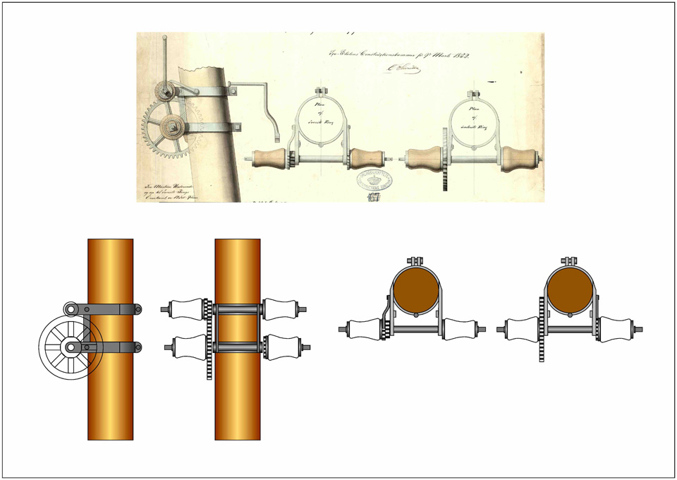
Working drawing for the cargo-winch attached to the mast
To be continued …
OK, turning the mast from 3 mm acrylic rod didn't work. First tried the larger watchmaker's lathe, but couldn't bring the fixed steady close enough to the point of work. Switched to the smaller lathe, which has a steady specially for thin material, but the rod still flexed and jumped over the cutting bit. Brass is siffer, but still not stiff enough I think. Have to go back reoentantly to steel - this will now call for some serious soldering and micro-metal work, not just cementing plastics.
Simply tapering the rod with wet-and-dry paper could perhaps have worked, but I like to turn-on the iron bands - looks much crisper than adding them later.
It's becoming to warm now in the workshop - another oncoming heatwave plus the internal heat from frustration. Have to give it a go at another day.
In between, I also drew the cargo winch, based on a drawing from the Danish archives for a little topsail schooner of 1852 (G-5204-17, https://arkivalieronline.rigsarkivet.dk/)
Working drawing for the cargo-winch attached to the mast
To be continued …
Eberhard
Former chairman Arbeitskreis historischer Schiffbau e.V. (German Association for Shipbuilding History)
--------------------------------------------------------------------------------------------------------------------------------------------------------------------------------------------
Former chairman Arbeitskreis historischer Schiffbau e.V. (German Association for Shipbuilding History)
--------------------------------------------------------------------------------------------------------------------------------------------------------------------------------------------
-
wefalck
- Posts: 2147
- Joined: Wed Sep 28, 2011 12:04 pm
- Location: Paris
- Contact:
Re: Pomeranian Rahschlup 1846 � 1/160 scale � Baltic trader
After a long, hot summer during which we endured five consecutive heat-waves that kind of paralysed all work-shop activities and after several weeks of absence due to vacations, I finally mustered enough (mental) strength to return to the project.
Machining the mast – next round
Ruefully I returned to my first choice of material for such small masts – steel, after the failed attempt with acrylic rod. Steel is so much stiffer. Still, the use of steadies was needed to prevent flexing during the turning. Unfortunately, due to the arrangement of the cross-slide on watchmaker’s lathe, where the longitudinal slide sits on top of the transversal slide, normal travelling steadies cannot be used. An added inconvenience is that travel of the longitudinal slide is only 54 mm, while the whole length of the mast is 123 mm. This means that the cross-slide had to repositioned twice to cover the full length
The steel I am using is copper-coated welding rod, which has very good machining properties, but is not 100% round. This means that the turning operation has to be completed in one set-up, so that one does not loose concentricity. In consequence, step-wise turning while keeping as much material as possible in the collet, as one could do otherwise, is not really feasible.
The operation began by turning a point on the rod that was to be supported in a hollow fixed centre in the tailstock. Based on the (dimensioned) working drawing shown earlier, the various steps and rings were formed by reducing the 3 mm rod to the different enveloping diameters along the mast. According to the spar table in the original drawing, the mast had the usual slight taper above the deck. To turn this the top-slide had to be given a very shallow angle of 0.3°, which had to be eyeballed on the graduation. It is better to begin with a slightly steeper taper, working from the thin end. This prevents the thicker end from becoming accidentally under-dimensioned. Making the angle progressively shallower, one can approach the correct angle.
During this operation, the steel-rod was supported against flexing by my shop-made mini-steady, which easily moves along the lathe-bed and thus can be used as quasi-travelling steady.
The taper still had to be evened-out with fine files and sandpaper, checking the diameter along its length with a small micro-meter.
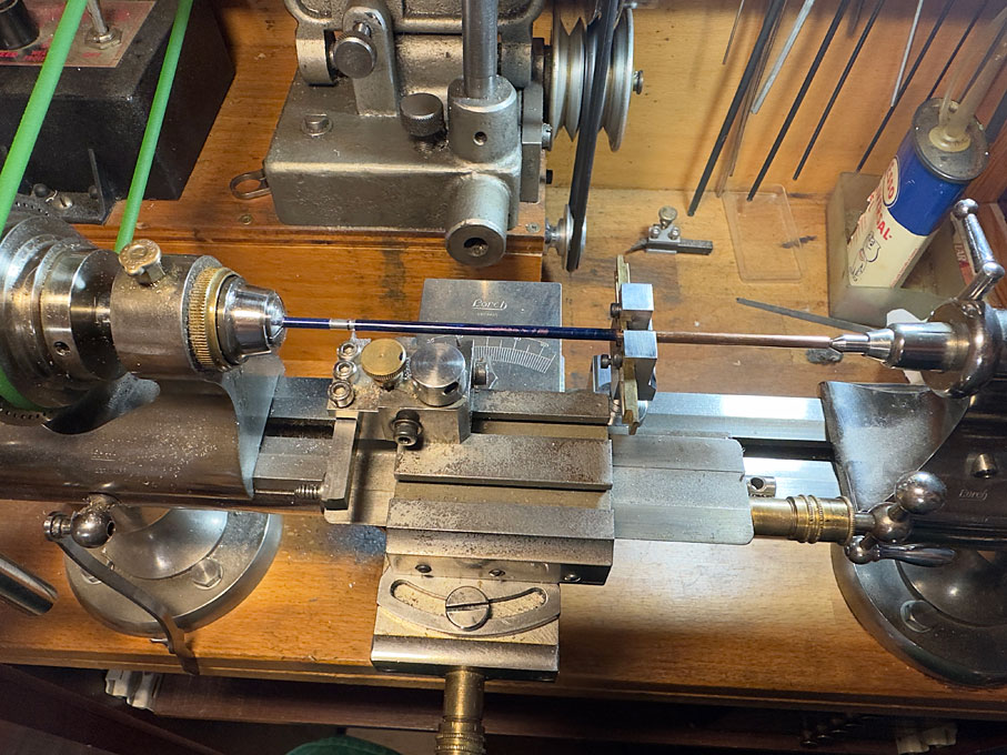
Set-up for turning the lower mast
The three ‘bands’ along the mast (two for the winch and one for the topmast-shrouds) were brought to the correct diameter as last operation on the lathe.
The various square sections of the mast were to be cut on the milling machine. For such operations I had adapted many years ago a watchmaker’s lathe bed as dividing attachment. The bed bolts to the table of the milling machine and can carry the same head- and tailstocks as the lathe, plus the various steadies to support slender work. The lathe-bed was trammed-in with a test indicator to ensure that it was parallel to the x-axis of the milling machine.
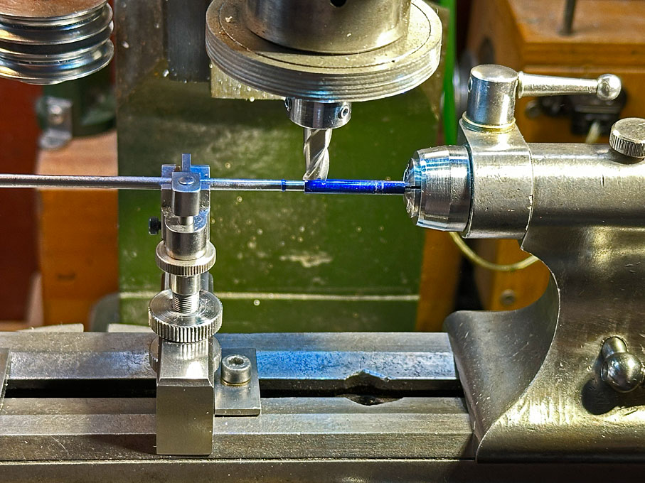
Set-up in the dividing attachment for milling the square onto the lower mast
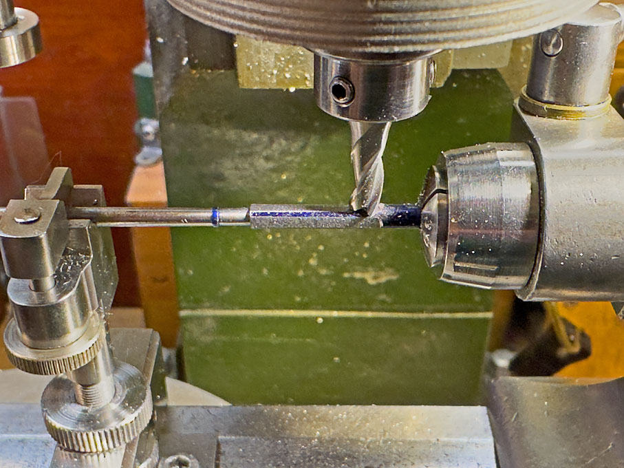
Close-up of the milling set-up before the operation
The raw mast was set up in the dividing attachment, supported by the tailstock and a kind of steady that I had built some years ago for such purposes. A ring with eight stops was chosen in the dividing head: the main faces to be milled are square, but the edges of the doubling will need to be chamfered 45° to prevent damage to the shrouds and main-stay.
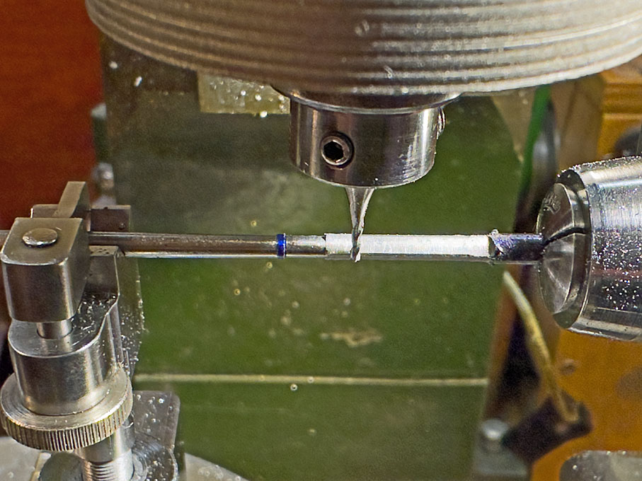
Chamfering the square doubling
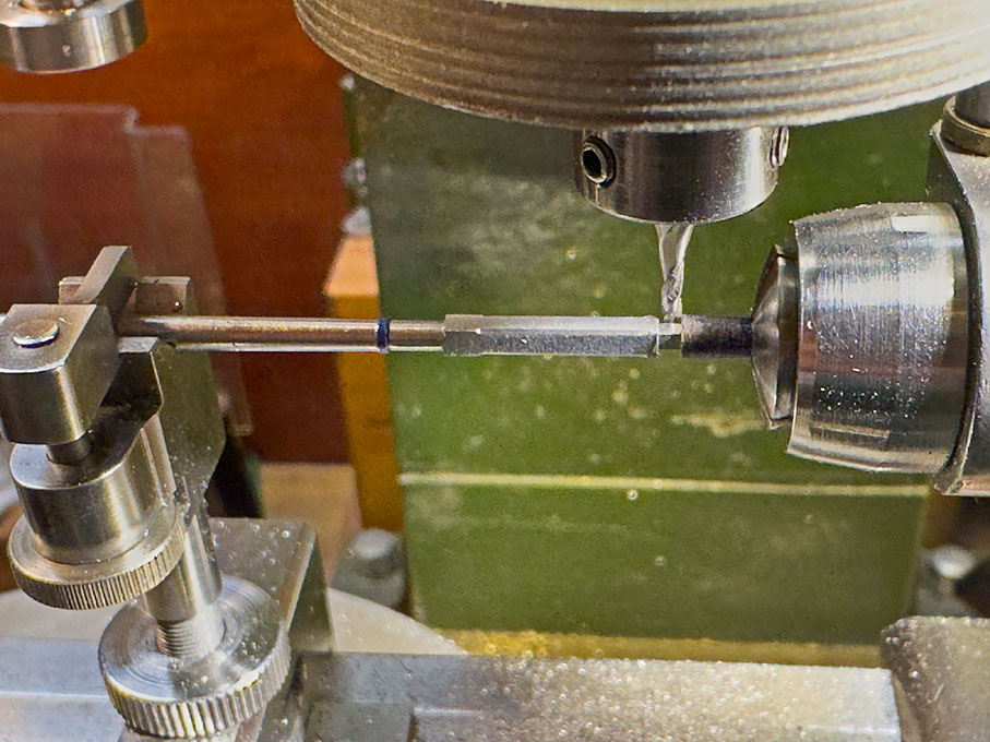
Milling the tenon for the mast-cap
In the same set-up the holes for eyebolts to attach the topmast shrouds had to be drilled. To this end, the spindle of the dividing head had to be locked firmly and the indirect dividing gear had to be set-up. This became necessary, because I realised that somehow, when I built the dividing attachment, I only drilled a ring with 6 instead of 12 holes (I have to rectify this at some stage).
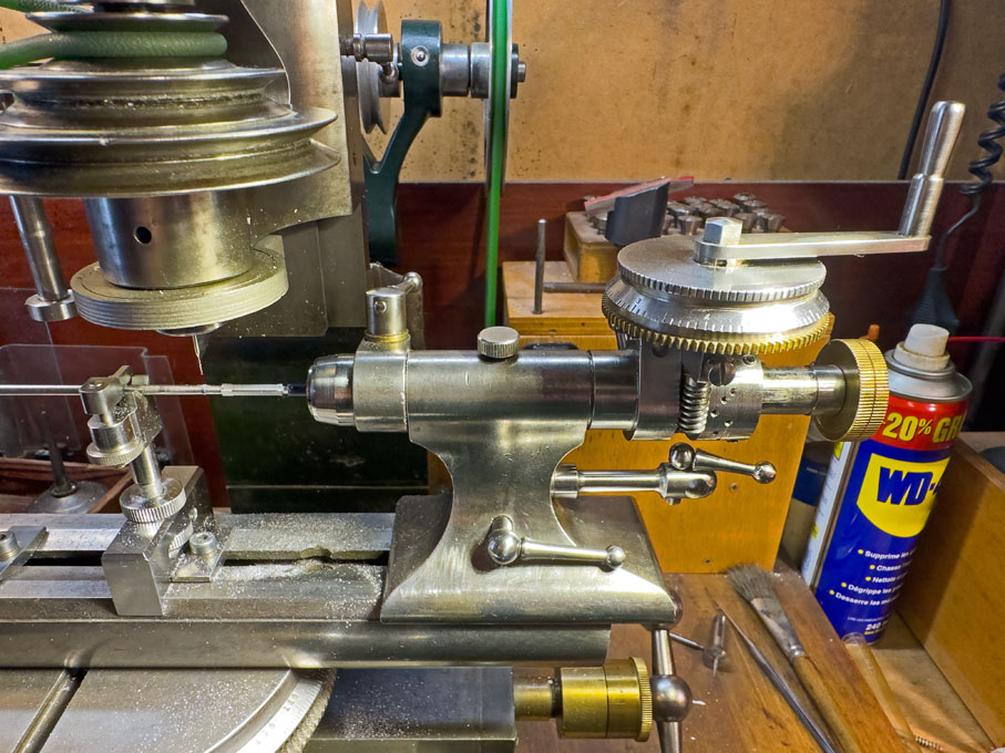
Set-up of the shop-made indirect dividing attachment
In the drawings I worked out that the eyebolts should be about 15° and -15° off the horizontal plane on either side. So, the necessary movements for indirect dividing were worked out. The holes were then spotted with a sharply pointed burr to prevent the drill from slipping on the round surface. Finally, the holes were drilled out with a 0.25 mm drill, which was a bit of a challenge on the big mill.
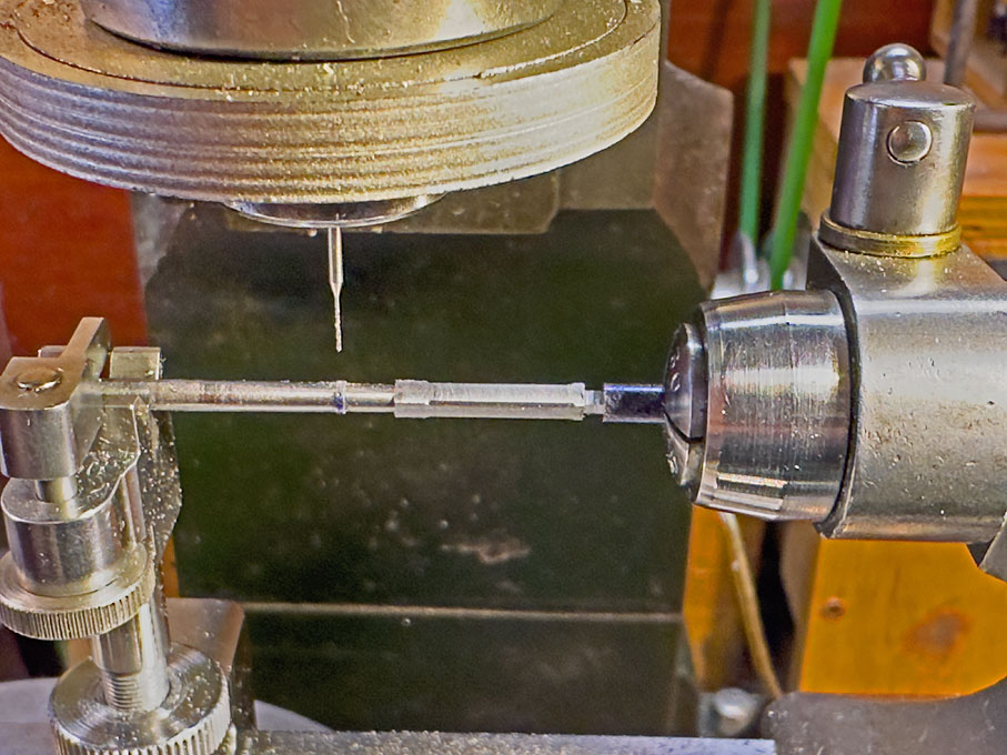
Drilling the holes for eyebolts in the spider-band
The mast was then returned to the lathe to cut off the excess material on both ends.
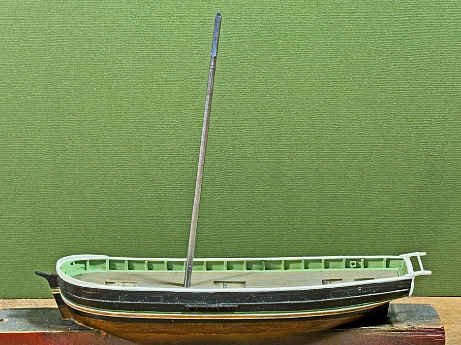
The lower mast provisionally stepped in the model
The next operations will be to make and solder on the cheeks and the eyebolts. Then the cross-trees have to be built.
To be continued …
Machining the mast – next round
Ruefully I returned to my first choice of material for such small masts – steel, after the failed attempt with acrylic rod. Steel is so much stiffer. Still, the use of steadies was needed to prevent flexing during the turning. Unfortunately, due to the arrangement of the cross-slide on watchmaker’s lathe, where the longitudinal slide sits on top of the transversal slide, normal travelling steadies cannot be used. An added inconvenience is that travel of the longitudinal slide is only 54 mm, while the whole length of the mast is 123 mm. This means that the cross-slide had to repositioned twice to cover the full length
The steel I am using is copper-coated welding rod, which has very good machining properties, but is not 100% round. This means that the turning operation has to be completed in one set-up, so that one does not loose concentricity. In consequence, step-wise turning while keeping as much material as possible in the collet, as one could do otherwise, is not really feasible.
The operation began by turning a point on the rod that was to be supported in a hollow fixed centre in the tailstock. Based on the (dimensioned) working drawing shown earlier, the various steps and rings were formed by reducing the 3 mm rod to the different enveloping diameters along the mast. According to the spar table in the original drawing, the mast had the usual slight taper above the deck. To turn this the top-slide had to be given a very shallow angle of 0.3°, which had to be eyeballed on the graduation. It is better to begin with a slightly steeper taper, working from the thin end. This prevents the thicker end from becoming accidentally under-dimensioned. Making the angle progressively shallower, one can approach the correct angle.
During this operation, the steel-rod was supported against flexing by my shop-made mini-steady, which easily moves along the lathe-bed and thus can be used as quasi-travelling steady.
The taper still had to be evened-out with fine files and sandpaper, checking the diameter along its length with a small micro-meter.
Set-up for turning the lower mast
The three ‘bands’ along the mast (two for the winch and one for the topmast-shrouds) were brought to the correct diameter as last operation on the lathe.
The various square sections of the mast were to be cut on the milling machine. For such operations I had adapted many years ago a watchmaker’s lathe bed as dividing attachment. The bed bolts to the table of the milling machine and can carry the same head- and tailstocks as the lathe, plus the various steadies to support slender work. The lathe-bed was trammed-in with a test indicator to ensure that it was parallel to the x-axis of the milling machine.
Set-up in the dividing attachment for milling the square onto the lower mast
Close-up of the milling set-up before the operation
The raw mast was set up in the dividing attachment, supported by the tailstock and a kind of steady that I had built some years ago for such purposes. A ring with eight stops was chosen in the dividing head: the main faces to be milled are square, but the edges of the doubling will need to be chamfered 45° to prevent damage to the shrouds and main-stay.
Chamfering the square doubling
Milling the tenon for the mast-cap
In the same set-up the holes for eyebolts to attach the topmast shrouds had to be drilled. To this end, the spindle of the dividing head had to be locked firmly and the indirect dividing gear had to be set-up. This became necessary, because I realised that somehow, when I built the dividing attachment, I only drilled a ring with 6 instead of 12 holes (I have to rectify this at some stage).
Set-up of the shop-made indirect dividing attachment
In the drawings I worked out that the eyebolts should be about 15° and -15° off the horizontal plane on either side. So, the necessary movements for indirect dividing were worked out. The holes were then spotted with a sharply pointed burr to prevent the drill from slipping on the round surface. Finally, the holes were drilled out with a 0.25 mm drill, which was a bit of a challenge on the big mill.
Drilling the holes for eyebolts in the spider-band
The mast was then returned to the lathe to cut off the excess material on both ends.
The lower mast provisionally stepped in the model
The next operations will be to make and solder on the cheeks and the eyebolts. Then the cross-trees have to be built.
To be continued …
Eberhard
Former chairman Arbeitskreis historischer Schiffbau e.V. (German Association for Shipbuilding History)
--------------------------------------------------------------------------------------------------------------------------------------------------------------------------------------------
Former chairman Arbeitskreis historischer Schiffbau e.V. (German Association for Shipbuilding History)
--------------------------------------------------------------------------------------------------------------------------------------------------------------------------------------------
-
marijn van gils
- Posts: 2750
- Joined: Tue Feb 06, 2007 10:24 am
- Location: Belgium
Re: Pomeranian Rahschlup 1846 � 1/160 scale � Baltic trader
Wow, those are not easy machining operations on such a thin piece, especially on steel!
Will you also drill the mast for pins to attach the yards? Or will the yards only be attached like the real thing?
Will you also drill the mast for pins to attach the yards? Or will the yards only be attached like the real thing?
-
wefalck
- Posts: 2147
- Joined: Wed Sep 28, 2011 12:04 pm
- Location: Paris
- Contact:
Re: Pomeranian Rahschlup 1846 � 1/160 scale � Baltic trader
It will be done like the 'real thing'. At this scale it is still possible. Also, at this stage of project development I don't know yet in what position the yards will be shown, though I have some ideas.
Actually, depending on the steel, is easier to machine and drill steel than e.g. brass. Brass has the tendency to hook and snag tools, as it is softer.
It is a bit of a challenge, nevertheless ...
Actually, depending on the steel, is easier to machine and drill steel than e.g. brass. Brass has the tendency to hook and snag tools, as it is softer.
It is a bit of a challenge, nevertheless ...
Eberhard
Former chairman Arbeitskreis historischer Schiffbau e.V. (German Association for Shipbuilding History)
--------------------------------------------------------------------------------------------------------------------------------------------------------------------------------------------
Former chairman Arbeitskreis historischer Schiffbau e.V. (German Association for Shipbuilding History)
--------------------------------------------------------------------------------------------------------------------------------------------------------------------------------------------
-
EJFoeth
- Posts: 2941
- Joined: Wed Jan 21, 2009 1:51 pm
Re: Pomeranian Rahschlup 1846 � 1/160 scale � Baltic trader
A small pin will not show though? I'm also contemplating to replace some mast parts and add a yardarm pin, plus a few holes to connect some pulley lines to (0.15mm? hope that works). That divider is a nice attachment, does not exist for my small Proxxon (which also saves $  ).
).-
wefalck
- Posts: 2147
- Joined: Wed Sep 28, 2011 12:04 pm
- Location: Paris
- Contact:
Re: Pomeranian Rahschlup 1846 � 1/160 scale � Baltic trader
We just have discussion over in MSW on the fact, that PROXXON so far does not offer a small indexing head with tailstock for the MF70 (and neither for the larger machines). This would be really useful for many modelling applications.
However, there are now on the market, ebay etc., parts from which one could easily built such attachments. They offer cheap lathes using brackets from CNC machines as tailstocks. You can get the brackets seperately with different IDs. There are straight arbors for ES7 collets and collet set for less than 30€. You can print different dividing disc to be mounted on the back of the arbor on your computer. All makeshift, but good enough for this kind of application. One has to be imaginative.
... and then, once you have put everything together, PROXXON will come out with just that thing
However, there are now on the market, ebay etc., parts from which one could easily built such attachments. They offer cheap lathes using brackets from CNC machines as tailstocks. You can get the brackets seperately with different IDs. There are straight arbors for ES7 collets and collet set for less than 30€. You can print different dividing disc to be mounted on the back of the arbor on your computer. All makeshift, but good enough for this kind of application. One has to be imaginative.
... and then, once you have put everything together, PROXXON will come out with just that thing
Eberhard
Former chairman Arbeitskreis historischer Schiffbau e.V. (German Association for Shipbuilding History)
--------------------------------------------------------------------------------------------------------------------------------------------------------------------------------------------
Former chairman Arbeitskreis historischer Schiffbau e.V. (German Association for Shipbuilding History)
--------------------------------------------------------------------------------------------------------------------------------------------------------------------------------------------
-
EJFoeth
- Posts: 2941
- Joined: Wed Jan 21, 2009 1:51 pm
Re: Pomeranian Rahschlup 1846 � 1/160 scale � Baltic trader
Very much doubt anything useful anytime soon for Proxxon, my smaller PD230 (light so easy to store) is missing several key features and has for many years. The only thing they changed is the quick tool post so that your old parts no longer fit well enough (just enough to be not fixed well). What I really miss is an accurate angle indicator for the top slide; you can rotate it, but then you can eyeball it to the nearest 5 degrees. I dare not change it and then use it again because I do not want to spend an hour calibrating it; some custom indicator with a nonius would probably come in handy. Tailstock cannot be calibrated and is almost nearly ok, but small drills are never exactly perfectly centered (deviation is tiny but it is there). And then there is no tailstock collet set, so you need to buy your own and then find out the tailstock has half an MC1 and you need to cut off half of the cone of the collet chuck or it won't fit (bewildering). Does that cause the offset I have? Perhaps (don't think so), but it is less than using drill chucks that are not very good so overall an improvement. I do not use the lathe than often anymore, so going to a new smaller one is too much of an investment right now in time and money, but otherwise I have reservations about the Proxxon. Not that I do not have a lot of fun with it from time to time....
-
wefalck
- Posts: 2147
- Joined: Wed Sep 28, 2011 12:04 pm
- Location: Paris
- Contact:
Re: Pomeranian Rahschlup 1846 � 1/160 scale � Baltic trader
I gather that is why I went down the watchmaking equipment road 40 years ago
There are limitations as well, because the lathes were designed for working on short parts mainly, but in terms of precision and finish they cannot be beaten by what's on the modellers' market today. The workholding options are also endless.
There are limitations as well, because the lathes were designed for working on short parts mainly, but in terms of precision and finish they cannot be beaten by what's on the modellers' market today. The workholding options are also endless.
Eberhard
Former chairman Arbeitskreis historischer Schiffbau e.V. (German Association for Shipbuilding History)
--------------------------------------------------------------------------------------------------------------------------------------------------------------------------------------------
Former chairman Arbeitskreis historischer Schiffbau e.V. (German Association for Shipbuilding History)
--------------------------------------------------------------------------------------------------------------------------------------------------------------------------------------------
-
EJFoeth
- Posts: 2941
- Joined: Wed Jan 21, 2009 1:51 pm
Re: Pomeranian Rahschlup 1846 � 1/160 scale � Baltic trader
What worries me is not knowing which brand is good (value for money), where to get spare parts, if the brand still exists, and so on.... I've seen sets on sale on watchmakers fairs... and not being a machinist making new parts is scary and before you know it the tool becomes a self-sustaining hobby by itself And your build shows that it very much is Choices, choices... Anyway, for drilling the Proxxon lathe so far has proven itself to be a very valuable addition too.
And your build shows that it very much is Choices, choices... Anyway, for drilling the Proxxon lathe so far has proven itself to be a very valuable addition too.-
wefalck
- Posts: 2147
- Joined: Wed Sep 28, 2011 12:04 pm
- Location: Paris
- Contact:
Re: Pomeranian Rahschlup 1846 � 1/160 scale � Baltic trader
The topmast
Once I had fitted the cheeks to the lower mast as planned, I realised that the cross-trees actually need to be fitted to the as-built state and not to as-designed in order ensure a snug fit. So, I turned my attention to the to topmast first.
As before this was fashioned from a length of 3 mm steel welding rod. In a first step, centres at both ends were turned on to facilitate the following machining operations.
Due to the square shape of the heel of the topmast this square was first milled in the dividing attachment on the milling machine.
In this set-up also a 1 mm hole was drilled through the heel for taking up the fid. Now, the fid has indeed a rectangular cross-section, but making a 0,5 mm x 0,3 mm rectangular hole through 2 mm of steel is well-nigh impossible with my tools (that would be an EDM job). So, the idea is to solder a 1 mm brass-in into the hole and then file the shape of the fid from this pin.
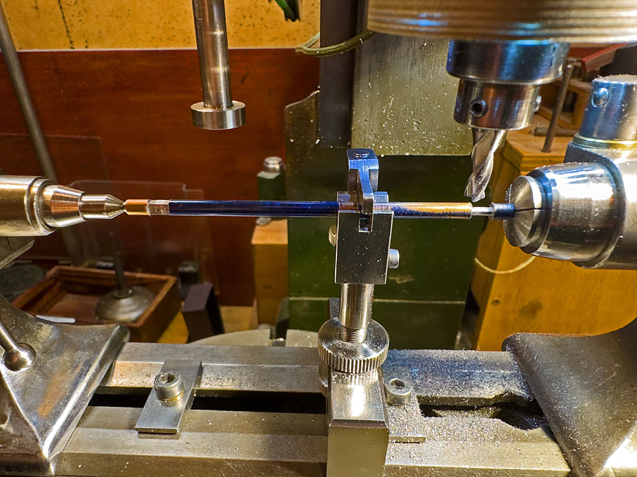
Set-up for milling the octagonal shoulder
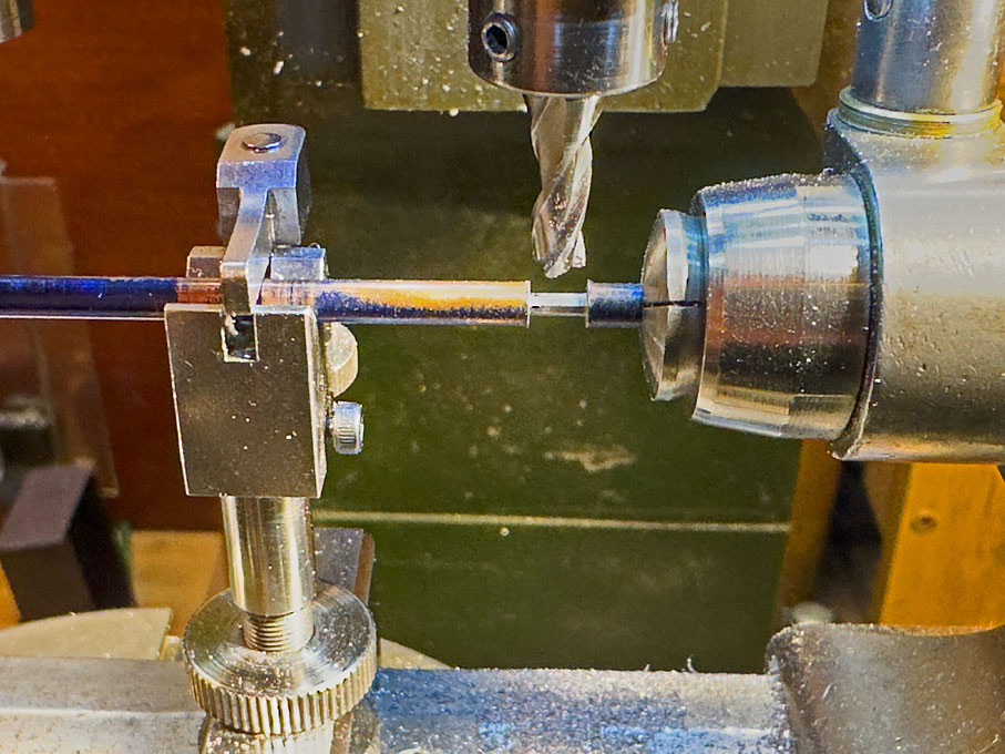
Milling the octagonal shoulder
The future topmast was then flipped over to mill the octagonal section that will form the shoulder for the topmast-shrouds and – backstays. Holding the section to milled close to the collet makes for a more rigid set-up. In the same set-up also a 0.4 mm through hole and two shallow blind holes from opposite sides were drill to simulate the sheave for the topgallant-yard halliard.
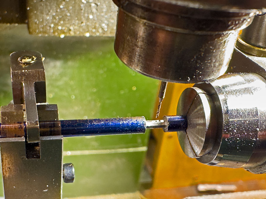
Drilling the sheave-holes into the octagonal shoulder
The topmast blank then was returned to the lathe. The CAD tells me that it’s taper has an included angle of about 1°, so that top-slide was offset by about 0.5° for turning. As the end of the tapered part transitions into a square resp. octagonal part, I used a round-tipped turning-tool that I had happened to lie around. I did not support the blank with a steady this time because it is actually quite stiff over the length of just over 50 mm and also the slight flexing in the middle gives a more pleasant and natural looking shape than a straight cone.
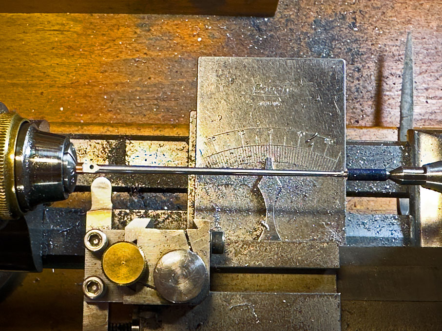
Taper-turning of the topmast with rounded transitions
Back on the mill the holes to remaining sheaves, for the topsail-halliard and for the halliard that is only rigged, when setting or striking the topmast, were drilled. The latter do not need to the through holes, as no rope will be rigged. While moving the part between the lathe and the mill entails the risk of loosing precision, it made drilling easier, as I only had to go through the thin topmast, rather than the 3 mm stock.
Finally, the topmast was returned to the lathe for parting off the stock at both ends. Contrary to good workshop practice this was done with the other end supported by the tailstock to avoid ‘whiplash injuries’ to the part. Again, the part was flipped over to allow parting off near the collet, which is of course much safer.
The next step was to solder a length of 1 mm brass rod into the heel, from which the fid will be fashioned in situ.
To be continued …
Once I had fitted the cheeks to the lower mast as planned, I realised that the cross-trees actually need to be fitted to the as-built state and not to as-designed in order ensure a snug fit. So, I turned my attention to the to topmast first.
As before this was fashioned from a length of 3 mm steel welding rod. In a first step, centres at both ends were turned on to facilitate the following machining operations.
Due to the square shape of the heel of the topmast this square was first milled in the dividing attachment on the milling machine.
In this set-up also a 1 mm hole was drilled through the heel for taking up the fid. Now, the fid has indeed a rectangular cross-section, but making a 0,5 mm x 0,3 mm rectangular hole through 2 mm of steel is well-nigh impossible with my tools (that would be an EDM job). So, the idea is to solder a 1 mm brass-in into the hole and then file the shape of the fid from this pin.
Set-up for milling the octagonal shoulder
Milling the octagonal shoulder
The future topmast was then flipped over to mill the octagonal section that will form the shoulder for the topmast-shrouds and – backstays. Holding the section to milled close to the collet makes for a more rigid set-up. In the same set-up also a 0.4 mm through hole and two shallow blind holes from opposite sides were drill to simulate the sheave for the topgallant-yard halliard.
Drilling the sheave-holes into the octagonal shoulder
The topmast blank then was returned to the lathe. The CAD tells me that it’s taper has an included angle of about 1°, so that top-slide was offset by about 0.5° for turning. As the end of the tapered part transitions into a square resp. octagonal part, I used a round-tipped turning-tool that I had happened to lie around. I did not support the blank with a steady this time because it is actually quite stiff over the length of just over 50 mm and also the slight flexing in the middle gives a more pleasant and natural looking shape than a straight cone.
Taper-turning of the topmast with rounded transitions
Back on the mill the holes to remaining sheaves, for the topsail-halliard and for the halliard that is only rigged, when setting or striking the topmast, were drilled. The latter do not need to the through holes, as no rope will be rigged. While moving the part between the lathe and the mill entails the risk of loosing precision, it made drilling easier, as I only had to go through the thin topmast, rather than the 3 mm stock.
Finally, the topmast was returned to the lathe for parting off the stock at both ends. Contrary to good workshop practice this was done with the other end supported by the tailstock to avoid ‘whiplash injuries’ to the part. Again, the part was flipped over to allow parting off near the collet, which is of course much safer.
The next step was to solder a length of 1 mm brass rod into the heel, from which the fid will be fashioned in situ.
To be continued …
Eberhard
Former chairman Arbeitskreis historischer Schiffbau e.V. (German Association for Shipbuilding History)
--------------------------------------------------------------------------------------------------------------------------------------------------------------------------------------------
Former chairman Arbeitskreis historischer Schiffbau e.V. (German Association for Shipbuilding History)
--------------------------------------------------------------------------------------------------------------------------------------------------------------------------------------------
-
wefalck
- Posts: 2147
- Joined: Wed Sep 28, 2011 12:04 pm
- Location: Paris
- Contact:
Re: Pomeranian Rahschlup 1846 � 1/160 scale � Baltic trader
The top
The trestle-trees resting on the cheeks were milled from 9 mm long section of brass bar with a 2 mm x 1 mm cross section. Slots for the cross-trees were milled to a snug fit of the 1mm square brass bar. The ends of the cross-trees were also slotted for the topmast-shrouds.
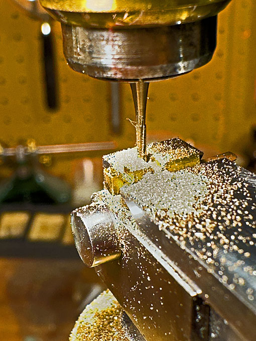
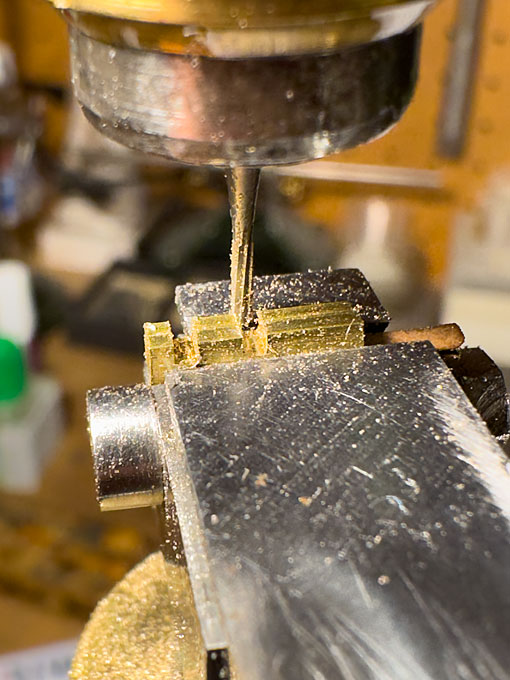
Slotting the trestle-trees for the cross-tree battens
The front cross-tree has a 0.75 mm square cross-section. Rather than milling this from brass, I cut a suitable length from a 0.75 mm square polystyrene profile.
The brass parts were carefully laid out on my soldering jig and silver-soldered together.
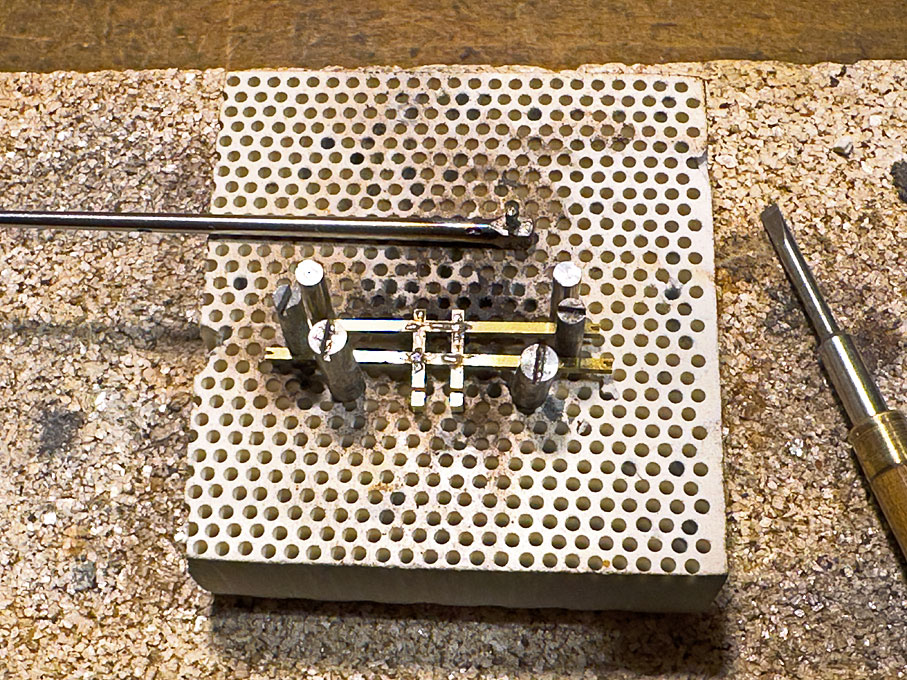
Soldering the top together on an adjustable soldering jig
The cross trees were slightly tapered towards the outside after assembling.
The cap was machined from a piece of 1,5 mm thick brass bar, but I did not take any pictures of this. For the 1.3 mm square mortice a 1.3 mm pilot hole was drilled that was then opened up with a 1 mm square file.
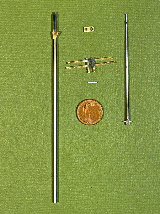
The parts for the mast laid out
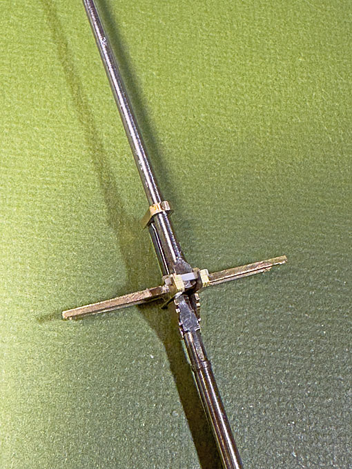
Close-up view of the assembled top
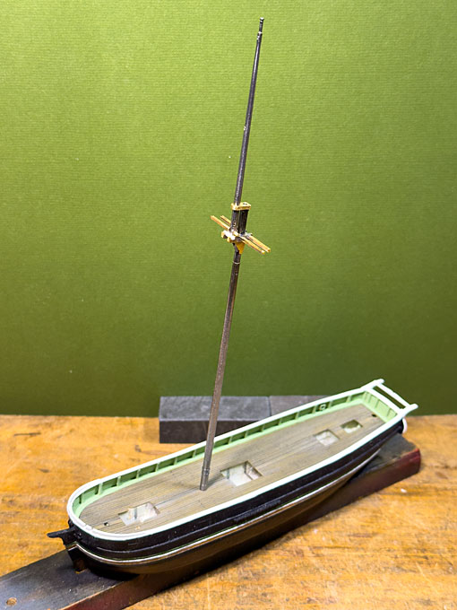
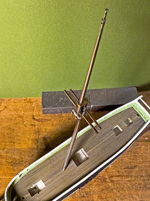
The mast stepped temporarily in the model
The lower mast still needs to have the eye-bolts for the futtock-shrouds soldered in, the shelf for the boom made and installed, and also the partners made and installed. Also, the cargo-winch needs to be made. However, as I have everything set-up for spar-making, I will turn my attention to the bowsprit and the jibboom first, perhaps also all the other spars. Before doing that, I will have to further develop the rigging plan, so that I am clear what bands and eyebolts are needed in the various spars.
To be continued …
The trestle-trees resting on the cheeks were milled from 9 mm long section of brass bar with a 2 mm x 1 mm cross section. Slots for the cross-trees were milled to a snug fit of the 1mm square brass bar. The ends of the cross-trees were also slotted for the topmast-shrouds.
Slotting the trestle-trees for the cross-tree battens
The front cross-tree has a 0.75 mm square cross-section. Rather than milling this from brass, I cut a suitable length from a 0.75 mm square polystyrene profile.
The brass parts were carefully laid out on my soldering jig and silver-soldered together.
Soldering the top together on an adjustable soldering jig
The cross trees were slightly tapered towards the outside after assembling.
The cap was machined from a piece of 1,5 mm thick brass bar, but I did not take any pictures of this. For the 1.3 mm square mortice a 1.3 mm pilot hole was drilled that was then opened up with a 1 mm square file.
The parts for the mast laid out
Close-up view of the assembled top
The mast stepped temporarily in the model
The lower mast still needs to have the eye-bolts for the futtock-shrouds soldered in, the shelf for the boom made and installed, and also the partners made and installed. Also, the cargo-winch needs to be made. However, as I have everything set-up for spar-making, I will turn my attention to the bowsprit and the jibboom first, perhaps also all the other spars. Before doing that, I will have to further develop the rigging plan, so that I am clear what bands and eyebolts are needed in the various spars.
To be continued …
Eberhard
Former chairman Arbeitskreis historischer Schiffbau e.V. (German Association for Shipbuilding History)
--------------------------------------------------------------------------------------------------------------------------------------------------------------------------------------------
Former chairman Arbeitskreis historischer Schiffbau e.V. (German Association for Shipbuilding History)
--------------------------------------------------------------------------------------------------------------------------------------------------------------------------------------------
-
JIM BAUMANN

- Posts: 5723
- Joined: Mon Jan 10, 2005 5:30 pm
- Location: Nr Southampton England
Re: Pomeranian Rahschlup 1846 � 1/160 scale � Baltic trader
That does look rather neat !
I am envious of your mast-up stage ...
regards
JB
I am envious of your mast-up stage ...
regards
JB
....I buy them at three times the speed I build 'em.... will I live long enough to empty my stash...?
http://www.modelshipgallery.com/gallery ... index.html
IPMS UK SIG (special interest group) www.finewaterline.com
http://www.modelshipgallery.com/gallery ... index.html
IPMS UK SIG (special interest group) www.finewaterline.com
-
wefalck
- Posts: 2147
- Joined: Wed Sep 28, 2011 12:04 pm
- Location: Paris
- Contact:
Re: Pomeranian Rahschlup 1846 � 1/160 scale � Baltic trader
Thanks, Jim, but the mast has only put in temporarily, so that I can determine e.g. the angle of the chains for the deadeyes of the shrouds and the tackles for the backstays.
Stay tuned ...
Stay tuned ...
Eberhard
Former chairman Arbeitskreis historischer Schiffbau e.V. (German Association for Shipbuilding History)
--------------------------------------------------------------------------------------------------------------------------------------------------------------------------------------------
Former chairman Arbeitskreis historischer Schiffbau e.V. (German Association for Shipbuilding History)
--------------------------------------------------------------------------------------------------------------------------------------------------------------------------------------------